
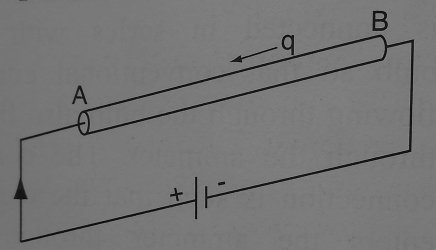
The potential difference between to points A and B (Vab) of a conductor is defined as the work done in moving unit charge from point B to A of the conductor.
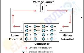
The figure below illustrates the movement of charge in a conductor under the influence of a potential difference.
One volt is equal to one joule per coulomb.
Potential difference is measured in volts using a voltmeter.
Work must be done to move an electric charge through a conductor. The device that does this work is referred to as the source of electromotive force (e.m.f).
The source of e.m.f could be a battery that converts chemical energy to electrical energy or a generator that converts mechanical energy to electrical energy.
The battery does the work of driving charges through a conductor or through an electrical device. When the battery is driving current, an electric potential difference (p.d) is said to have developed between it’s ends. The potential difference is measured in volts by a voltmeter.
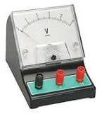
The figure below shows an analog voltmeter common in school laboratories.
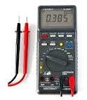
The figure below shows digital voltmeter in use.
Example problem 1
360 joules of work had been used to move 50 coulombs of charge through a conductor. What is the potential difference between the two ends of the conductor?
solution
Current and potential difference for parallel circuit arrangements
consider the circuit below
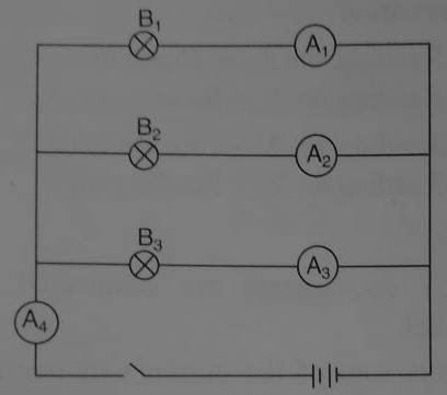
Each of the ammeters A1, A2 and A3 each will measure different current. The current on ammeter A4 is the sum of currents from the three ammeters in parallel. in other words, the sum of currents in parallel circuits is equal to the total current. Each of the bulb will attract current from the battery depends on it’s resistance value.
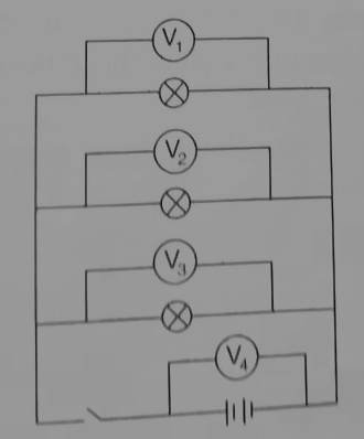
If we connect voltmeters across each of the bulbs as in figure below, they will all read same voltage. Voltage from each of the bulbs will be the same as the voltage across the cell when current is flowing.
Example Problem 2
The figure below shows current passing through three bulbs in parallel.
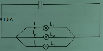
Determine the current passing through L1 given that 1.8 A is passing through the battery, 0.72 A through L2 and 0.35 A through L3 .
Solution
Current through the battery = current through L1 + current through L2 + current through L3
1.8 A = I1 + I2 + I3
1.8 A = I1 + 0.72 A + 0.35 A
1.8 A = I1 + 1.07 A
I1 = 1.8 A – 1.07 A
I1 = 0.73 A
Current and voltage for components in series
consider the setup below where bulbs have been arranged in series.
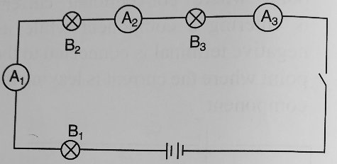
The ammeters A1, A2 and A3 all reads the same current. This shows that same current passes through the bulb in series.
when voltmeters are connected across each of the bulb, the voltage is different in each of the bulb. If the bulbs are identical, they have the same resistance. The voltage from the battery is shared equally among them.
consider the setup shown.
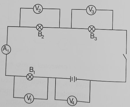
The reading on each of the voltmeters shows that the potential difference across the bulb have been shared equally among the identical bulbs.
The total voltage drops V1, V2 and V3 across the bulbs equals to the total voltage V4 from the battery.
From the observations, we concludes that:
- The same current flows through each components in series arrangement.
- The sum of voltage drop across the components is equal to the voltage supplied by the bulb
Related Topics
- Electromagnetic Induction
- Arrangement of components in a circuit: concise Detailed approach
- Factors that affects magnitude of the induced e.m.f
Leave a Reply