Determining Focal length from lens formula involves doing experiments to find different positions of image while adjusting object positions.
Focal length of a lens can be determined by investigating relationship between image distance and object distance by obtaining image distances from varying object distances.
The mirror formula describes the relationship that exists between the focal length, image distance and the object distance. Using the mirror formula derived earlier, We describe the experiment here and explains how to extract the the focal length from the relationship.
The mirror describes the relationship that exists between the focal length, image distance and the object distance.
The unknown Focal length of a lens can be determined experimentally by use of lens formula derived earlier. We describe the experiment here and explains how to extract the the focal length from the relationship.
We draw the graph of the of reciprocal values of image distance against the reciprocal values of object distance. The intercept of the graph is used to estimate the focal length of the lens used.
Apparatus
- Metre rule
- lens and a lens holder
- source of light
- screen
- cardboard with a cross wire
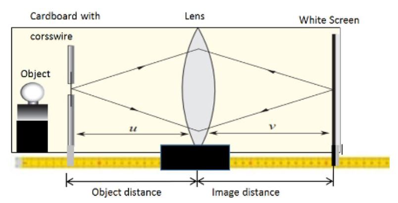
procedure
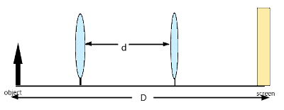
- set the apparatus as shown

- You place the object at the zero centimeter mark
- set the object distance by placing the lens at a reasonable distance from the object like 80cm from the object.
- Adjust the screen to observe a sharp image on the screen.
- Record a distance between the screen and the lens where you spot a sharp image on the screen is the image distance.
- Record the image and the object distance
- Reduce the object distance u by about 5 cm then adjust the screen until you see another sharp image on the screen.
- reduce the distances distance again by 5 cm and repeat the procedure above.
- Fill the table as shown below

From the data obtain a graph of 1/u against 1/v by plotting.
A typical graph will be as shown:

Graphical analysis of the Lens formula
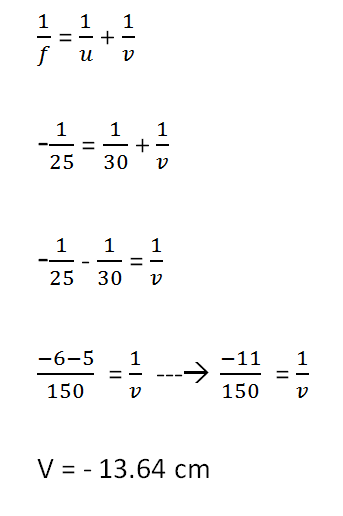
The lens formula is stated as:
1f=1u+1v
From the above formula, one can see that the sum of reciprocals of the image length from the lens and the reciprocal of the image distances equals reciprocal of the focal length.
At the (1/v) intercept the value of (1/u)= 0. The lens formular becomes:
1f=0+1v
We eliminated 1/u from the formula after it become zero such that:
1f=1v
The value of f-1 (1/f) is equal to 1/v meaning that we can approximate the reciprocal of f as the reciprocal of the image distance v read at the intercept.
At the (1/u) intercept, the the value of (1/v) =0. The lens formula becomes
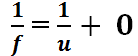
1f=1u+0
The formular is reduced to be as follow:
1f=1u
Determining the Focal length from lens formula
as a process of Determining Focal length from lens formula, from the graph, we can deduce that 1/u and 1/v gives reciprocal of the Focal length 1/f at the intercepts.
we can get two values of f from the 1/v and 1/u intercepts such that:
f1=(1V)−1andf2=(1U)−1
The focal length f is the average of f1 and f2 such that:
f=f1+f22
Question for practice
The table below shows values of object distance u and corresponding value of image distances a for a convex lens.
| object distance u(cm) | 10 | 15 | 20 | 25 | 30 | 35 |
| image distance v(cm) | 40.0 | 17.1 | 13.1 | 11.8 | 10.9 | 10.4 |
a table showing relationship between image distance and object distance
plot a suitable graph and from the graph determine the focal length of the lens.
Related Topics
- precisestudy.net
- Estimating focal length of a lens
- Ray diagrams: thin lenses
- Deriving the lens formula
- Determining the focal length of a convex lens
- Introduction to Photo electric effects
References:
- Secondary Physics Student’s Book Four. 3rd ed., Kenya Literature Bureau, 2012. pp. 1-42.
- Abbot A. F. (1980), Ordinary Level Physics, 3rd Edition, Heinemann Books International,
London. - Nelkon M. and Parker P., (1987), Advanced Level Physics, Heinemann Educational
Publishers, London. - Tom D., and Heather K. Cambridge IGCSE Physics. 3rd ed., Hodder Education, 2018, https://doi.org/978 1 4441 76421. pp. 106-142.