Introduction
Rotation is one of the most important transformations in Geometry. It is used in Mathematics, Engineering, Architecture, Computer Graphics, Robotics, Astronomy, and many other scientific fields.
Whenever an object turns about a fixed point, the transformation is called a rotation.
Examples of rotation in everyday life include:
- Opening and closing a door
- The hands of a clock
- A ceiling fan
- A bicycle wheel
- A spinning top
- A propeller
- A merry-go-round
In each case, the object turns about a fixed point known as the centre of rotation.
What is Rotation?
Rotation is a transformation that turns an object about a fixed point called the centre of rotation through a specified angle and direction.
Unlike enlargement, rotation does not change the size of an object.
The shape, size and distances between corresponding points remain unchanged.
Rotation is therefore classified as an isometry.
Key Terms
| Term | Meaning |
|---|---|
| Centre of Rotation | Fixed point about which an object turns |
| Angle of Rotation | Amount of turning measured in degrees |
| Direction of Rotation | Clockwise or Anticlockwise |
| Image | New position of the object after rotation |
| Object | Original figure before rotation |
Measuring Rotation
The angle of rotation is measured in degrees.
Common Rotations
| Rotation | Angle |
|---|---|
| Quarter Turn | 90° |
| Half Turn | 180° |
| Three-Quarter Turn | 270° |
| Full Revolution | 360° |
Illustration

Observe how the arrow changes direction after each turn.
- Quarter Turn = 90°
- Half Turn = 180°
- Three Quarter Turn = 270°
- Full Revolution = 360°
Direction of Rotation
There are two possible directions of rotation.
1. Clockwise Rotation
A rotation in the same direction as the hands of a clock.
2. Anticlockwise Rotation
A rotation opposite to the direction of the hands of a clock.
the figure below illustrates rotation of clockwise and anticlockwise rotation of 90o about the origin

Sign Convention
Mathematicians use signs to indicate the direction.
| Direction | Sign |
|---|---|
| Anticlockwise | Positive (+) |
| Clockwise | Negative (-) |
Examples:
- +90° means 90° anticlockwise
- -90° means 90° clockwise
- +180° means 180° anticlockwise
- -150° means 150° clockwise
Rotation Through 90°
A rotation through 90° is called a quarter turn.
Construction Procedure
Suppose triangle ABC in the figure below is rotated through +90° about point P.

- Join P to A.
- Measure PA.
- Draw a 90° angle from PA.
- Mark point A’ such that:
PA = PA’
- Repeat for points B and C.
- Join A’, B’ and C’.
The figure A’B’C’ is the image of triangle ABC.
Important Observation
When a figure is rotated:
- A’B’ = AB
- B’C’ = BC
- A’C’ = AC
Therefore:
Rotation preserves size and shape.
Illustration

Rotation Through 180°
A rotation through 180° is called a half turn.
Construction Procedure
Suppose triangle PQR is rotated through 180° about point O.
- Join P to O.
- Extend line PO.
- Mark P’ such that:
PO = OP’
- Repeat for Q and R.
- Join P’, Q’ and R’.
The resulting triangle is the image of triangle PQR.
Observation
For a 180° rotation:
- Corresponding sides remain equal.
- Corresponding sides become parallel.
Therefore:
Hence:
Object Size = Image Size
Illustration

Rotation Through 360°
A rotation through 360° is called a full revolution.
When an object is rotated through 360° about any point:
The image coincides exactly with the original object.
In other words:
A figure rotated through 360° maps onto itself.
Properties of Rotation
Rotation has several important properties.
Property 1: Rotation is an Isometry
The size of the figure remains unchanged.
Property 2: Lengths are Preserved
Corresponding sides remain equal.
Property 3: Angles are Preserved
Corresponding angles remain equal.
Property 4: Shape is Preserved
No distortion occurs.
Property 5: Orientation Changes
The position of the object changes although its size remains unchanged.
Worked Example 1
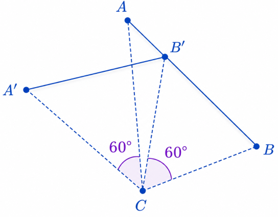
Rotating a Line Through 60°
Line AB is rotated through 60° about point C.

Find the image A’B’ under this rotation
Solution
- Join B to C.
- Measure CB.
- Construct angle BCB’ = 60°.
- Mark B’ such that:
BC = BC’
- Repeat the procedure for point A.
- Join A’ to B’.
The resulting line A’B’ is the image of line AB.
Illustration

Worked Example 2
Rotating Triangle PQR Through -150°
The triangle PQR is rotated through -150° about point O.

Solution
- Join P to O.
- Construct angle POP’ = 150° clockwise.
- Mark P’ such that:
OP = OP’
- Repeat for Q and R.
- Join P’, Q’ and R’.
The resulting triangle is the required image.
Illustration

Finding the Centre of Rotation
Sometimes both the object and its image are given.
The task is to determine the centre of rotation.
Example:
Triangle ABC is mapped onto a triangle A’B’C’ under a certain rotation.

Procedure
Step 1
Join a point and its corresponding image.
For example:
C to C’
Step 2
Construct the perpendicular bisector.
Step 3
Repeat using another pair of corresponding points.
For example:
B to B’
Step 4
The intersection of the two perpendicular bisectors is the centre of rotation.
Illustration

Finding the Angle of Rotation
Once the centre of rotation has been found:
- Join the centre to a point on the object.
- Join the centre to the corresponding point on the image.
- Measure the angle between the two lines.
This angle is the angle of rotation.
observations
For triangle ABC and image A’B’C’:
∠COC’ = 110°
Therefore:
- Angle of rotation = -110°
- Equivalent positive angle = 250°
Both answers describe the same rotation.
Example: Finding the Centre and Angle of Rotation of WX
Suppose line segment WX is mapped onto W’X’.

Solution
- Join W to W’.
- Join X to X’.
- Construct perpendicular bisectors.
- The bisectors meet at O.
Therefore:
O is the centre of rotation.
Measure:
∠WOW’ = 60°
Hence:
Angle of rotation = 60°
or
Angle of rotation = -300°
Illustration

Rotation Rules in Coordinate Geometry
For rotations about the origin:
90° Anticlockwise rotation
(x, y) → (-y, x)
Example:
(3, 2) → (-2, 3)
180° Rotation
(x, y) → (-x, -y)
Example:
(3, 2) → (-3, -2)
270° Anticlockwise Rotation
(x, y) → (y, -x)
Example:
(3, 2) → (2, -3)
360° Rotation
(x, y) → (x, y)
The point remains unchanged.
Interactive Activity
Try the rotation simulator below.
Students should:
- Rotate shapes through 90°, 180°, 270° and 360°.
- Observe how distances remain constant.
- Compare clockwise and anticlockwise rotations.
- Investigate how changing the centre of rotation affects the image.
Rotation Simulator
Explore rotations of a shape about a centre. Observe that distances from the centre remain constant.
Click anywhere on the canvas to change the centre of rotation.
Practice Questions
Question 1
A triangle is rotated through +90° about point O. What type of turn has occurred?
Question 2
Describe the image of a figure after a 180° rotation.
Question 3
A point (4, 2) is rotated 90° anticlockwise about the origin. Find its image.
Question 4
A figure is rotated through 360°. Describe the image.
Question 5
Explain how the centre of rotation can be determined when both the object and image are given.
Summary
Rotation is a transformation that turns a figure about a fixed point called the centre of rotation.
Key facts:
✓ Rotation preserves size and shape.
✓ Rotation is an isometry.
✓ Positive angles indicate anticlockwise rotation.
✓ Negative angles indicate clockwise rotation.
✓ Common angles are 90°, 180°, 270° and 360°.
✓ The centre of rotation can be found using perpendicular bisectors.
✓ The angle of rotation can be measured from corresponding points and the centre of rotation.
Understanding rotation provides a foundation for advanced studies in coordinate geometry, trigonometry, matrices, computer graphics and engineering.