
An electric current is the rate of flow of charge through a conductor. Electric current is measured in amperes by an instrument called ammeter.
An ammeter is an electrical instrument used to measure the current flowing through a circuit. The ammeter is designed to be connected in series with the circuit. This ensures that the current flows through the ammeter, allowing it to accurately measure the amount of electrical current.
There are two types of ammeters:
- Analog Ammeter: This uses a needle or pointer to indicate the current on a scale.
The figure below shows an analog ammeter ammeter common in school laboratories.

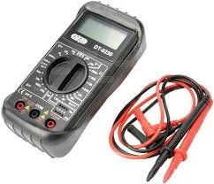
2. Digital Ammeter: This displays the current measurement on a digital screen. It provides a digital readout of the electrical current. Digital ammeter allows one to choose a scale of measurement in amperes (A), milli-amperes (mA), or microamperes (µA). It uses a numerical display rather than a moving needle or pointer.
Electric current flows between two points in a closed path due to a potential difference between those two points. Sometimes the flowing current can be too small to me measured by an ammeter. A more sensitive instrument may therefore be required to measure small currents.
A millimeter is an instrument used to measure current in terms of one in thousand of an ampere. A milliammeter measures current in terms of milli-amperes.
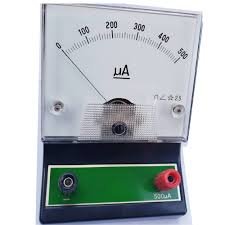
Much smaller currents can be measured by a micro- ammeter. A micro-ammeter measures current in terms of micro-ampere.

Using an ammeter in measuring electric current
An ammeter has very low electrical resistance. Therefore it is connected in series with the instrument whose current passing through need to be measured. When connecting an ammeter in the circuit, ensure it is done correctly. The correct procedure is such that current enters the ammeter through positive terminal and exits through the negative terminal. If connected such that convectional current enters through negative terminal, the ammeter may get damaged.
The figure below shows the ammeter connected in series with the bulb. The convectional current flowing through the bulb also flows through the ammeter.

The figure below shows wrong ammeter connection. Note that the positive terminal of the ammeter is connected to the negative terminal of the cell.

Before connecting the ammeter in a circuit, confirm that it’s pointer is at zero mark on the scale. Otherwise, use the zero adjusting screw to move it to the correct position. Most of ammeters has two scales. An appropriate scale should be selected to safeguard the coil from damaged if current passing exceeds its capacity. For example an ammeter can have a scale of (0-3)A or (0-5)A. The figure below shows an ammeter dashboard with two scales; (0-5)A and (0-2.5)A.

If a scale of (0 – 5) A is selected, the meter can read up to 5A. With such a scale, 10 divisions represents 1.0 A. For a (0-2.5) A scale, ten divisions will represent 0.5 A meaning each division is 0.05 A. From the diagram, the reading on the ammeter is 2.45 A while reading (0-5) A or 1.225 while reading the (0 -2.5) A.
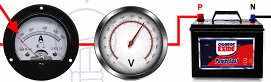
How to use voltmeter to measure potential difference
A voltmeter is always connected across the device (parallel to the device) which the voltage is to be measured. The figure below shows voltmeter connected across the bulb in parallel arrangement.

Voltmeter is connected in series because it is an instrument with high resistance to the flow of current. Therefore, It takes no current from the component across which the voltage is to be measured.
The positive terminal of the voltmeter is connected to the point where convectional current is entering a component. Its negative terminal is connected to the point where the current is leaving the component.
One should ensure that the pointer is exactly on the zero mark before connecting the voltmeter. If pointer is not at zero, the pointer should be adjusted to zero by the screw.
Leave a Reply