
Electric circuits are pathways through which electric current flows. Simple Electric Circuits are circuits made using simple apparatus and procedure.
An electric current is the flow of electric charge through a conductor, such as a wire. It occurs when charged particles move. Typically, electrons respond to an electric field created by a voltage difference across the conductor. Voltage difference is provided by a cell or a battery.
A cell is a device that converts chemical energy into electrical energy, providing a source of electrical power. It consists of one or more electrochemical reactions that generate a flow of electrons, which is the electric current. A battery is a combination of two or more cells.
The figure below shows a dry cell that is common in making of many simple circuits.

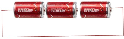
The figure below three dry cells connected to make a battery:
Cell provides the energy required to pump electrons in a conductor so that they can move in a closed loop. A cell creates voltage difference by creating a region of excess electrons on one side and deficit of electrons on the other side through chemical reactions. A conductor is connected such that it runs from one side of the cell to the other in a closed loop.
When there is no gap between the two ends of the cell or battery along the conductor, the circuit is said to be complete. Charge flows only when the circuit is complete. Cell acts as the pump to push the charges along the conductor so that they can be on the move.
The end of battery with excess of negative charge is called the negative terminal. The other end with with deficit of charge is known as the positive charge. Charge flows from negative terminal of a cell towards the positive terminal. Current flows in opposite direction conventionally form positive terminal of the battery towards the negative end. Current is when charges flow and is a function of the speed of flow of charges. Infact the formal definition of current is that current is the rate of flow of charges. The standard international unit of current is called Ampere (A).
From the definition of current:
charge is measured in coulombs while time is in seconds. Therefore Ampere is the number of coulombs per second.
Example:
What is the current flowing through a bulb where 100 coulombs of charge is observed to flow for 1.8 minutes?
solution
Example 2:
what amount of charge could be flowing through a conductor where current flowing is 6.0A
solution
Q = 6.0 coulombs
Making of Simple Electric Circuits
A simple electric circuit consists of a few basic components arranged in a loop that allows electric current to flow. The most basic components of a simple circuit includes:
Power Source
This is typically a battery or a cell that provides the electrical energy to push the charge around the circuit. The positive and negative terminals of the power source create a voltage difference that drives the current.
Conductor
These connect the components of the circuit and provide a path for the current to flow. The most common material to make conductors is copper wires. Other useful material to make electric current is aluminum wire. other wise most of metallic materials can conduct electric current.
Load
A load is any component that uses electrical energy. It performs a function, such as a light bulb, motor, or resistor. The current passes through the load, and energy is transferred to it (e.g., light or heat).
Switch
A switch is used to control the flow of current in the circuit. When the switch is open, the circuit is incomplete, and current does not flow. When the switch is closed, the circuit is complete, and current flows.
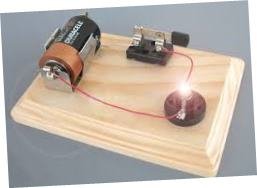
The simplest of electric circuit is made up battery and a conductor.

This circuit above is simple and naive , to make a working circuit, you need to some few extra components.
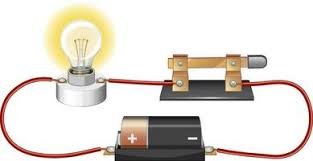
The bulb is used to show that current is flowing when the bulb lights. Opening the switch makes the bulb off showing that current off have been cut off. Current is conventionally set to flow opposite direction to the flow of charge.
Convectional Circuit Diagram
For clarity and neatness, symbols are used in representing components of an electric circuit. It would be tedious and clumsy to draw each of the components used in circuits. Therefore, we use symbols so that we can easily represent circuits in diagrams.
The figure below shows the circuit that was shown above drawn in convectional ways using symbols.

On the diagram above, there is a gap on the switch. The loop from the positive terminal of the cell towards the negative one has a gap. The circuit is said to be incomplete or open. No current is flowing in such circuit and is usually referred as an open circuit.
Switch acts like a gate, it connects two parts to make the circuit complete. When switch is closed, the circuit becomes complete. The figure below shows a complete circuit.
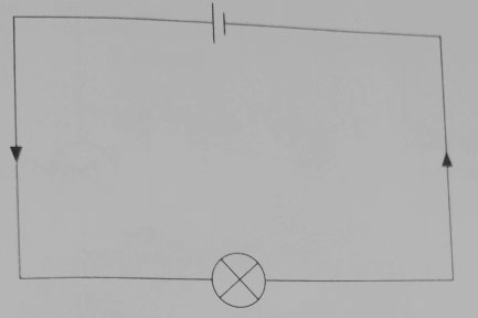
In the diagram below, current will flow from positive of the battery to the negative without encountering a gap. the bulb with thus light because it is in a closed circuit.
While drawing or interpreting circuit diagrams, Connecting wires are drawn as straight lines with right angle corners, although the actual wires are flexible and bent.
The arrow-heads drawn on the lines indicates direction of the flow of current. Remember that, current flows opposite direction to that of charge flow.
Short circuiting
Short circuiting is a condition where an electric current is caused to flow through a path of low resistance to avoid the path with high resistance. Electric current usually follows a path of least resistance when moving.
consider the figure below.
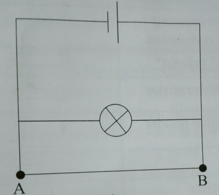
Bulb is considered to be of much higher resistance compared to the conducting wire. In the above connection, current will flow through wire AB and avoid passing through the bulb. The bulb with thus not light and is said to be short circuited. In the figure above, both the cell and the bulb are short circuited.
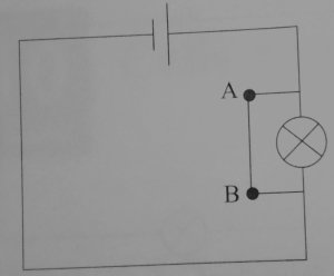
In the figure below only the bulb is short circuited.
Common electrical symbols used in circuit diagrams
each component in a circuit diagram has a unique symbol that represent it. The table below summarizes information about most of components used in circuit diagrams and their symbols.
| Symbol | Component name |
|---|---|
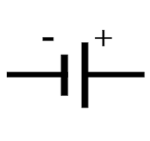 | cell |
 | battery |
| switch | |
 | bulb |
| filament lamp | |
 | wires crossing without connecting |
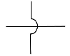
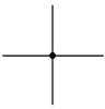 | wires crossing with connection |
| Fixed resistor | |
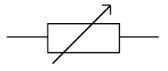 | variable resistor |
 | potential divider |
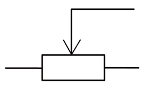
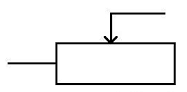 | rheostat |
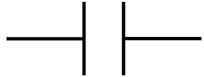 | capacitor |
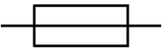 | fuse |
| Ammeter | |
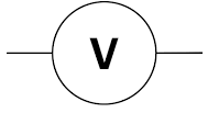 | voltmeter |
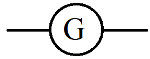 | Galvanometer |
Related topics
- Charging bodies in electrostatics
- Electric field patterns: Easy
- Introduction to Photo Electric Effect
- The law of charges
- Electrostatics 1
- Induced Electromotive Force
- Factors that affects magnitude of the induced e.m.f
Leave a Reply