Electromagnetic induction is a fundamental concept in physics that explains how electricity can be generated from a changing magnetic field. Whenever the magnetic flux linking a conductor changes, an electromotive force (EMF) is induced in the conductor. However, the magnitude of the induced EMF is not always the same; it depends on several factors that influence the rate at which the magnetic flux changes. Understanding these factors is essential for explaining the operation of electrical devices such as generators, transformers, and induction coils. In this article, we will explore the key factors that affect the magnitude of an induced EMF and examine how each factor contributes to the efficiency of electromagnetic induction.
The amount of current produced from changing magnetic flux depends on a number of factors which includes:
- Rate of change of magnetic flux
- strength of magnetic field
- number of turns in a coil
i. Rate of change of magnetic flux
The faster the rate of change of magnetic field, the higher the magnitude of the induced current.
Consider a coil of about 200 turns of a wire, sensitive galvanometer and a magnet arranged as shown in figure below.

To investigate how rate of change of magnetic flux, you move the magnet towards the coil and away at various speeds such as very fast, moderately fast and slowly.
You observe that the faster the magnet is moved to and from the coil, the higher the deflection on the galvanometer. This shows that induced EMF is highest when the rate of change of magnetic flux is highest.
Magnetic flux could be interpreted as the number of magnetic field touching the coil at any given moment.
Explanations
Magnetic flux Φ is the strength of magnetic field threading a given area.
The magnetic flux Φ changes when the magnet is withdrawn from the coil where a faster withdrawal gives rise to a higher rate of change in magnetic flux linking the coil which then gives an increased induced Electromotive force(e.m.f)
see the diagram below that shows magnetic field lines:

ii. strength of magnetic field
Moving a stronger magnetic towards or away from the coil causes increase of the induced current when the speed of movement remains constant.
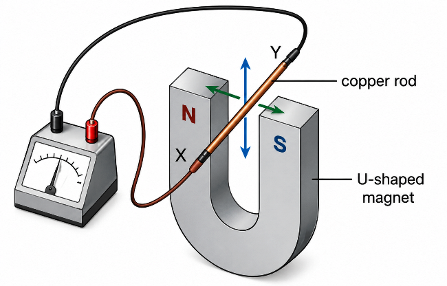
Consider a u-shaped electromagnet and a variable resistor connected to a circuit shown such that an electromagnet can have it’s strength varied by changing current passing through using the variable resistor.

After the setup, you can do the following to investigate the current induced with strength of the magnet:
- Adjust the variable resistor so that minimum current flows.
- Move the conductor PQ in a direction perpendicular to the magnetic field of the electromagnet and note deflection on the galvanometer.
- change values of current and record corresponding readings on the galvanometer when wire cuts across the magnetic field.
Observations
Whenever current through the ammeter is increased, a greater deflection is obtained on the galvanometer when the conductor wire cuts across the magnetic field.
Explanations
Higher current passing through a coil of wire leads to a stronger electromagnet that will produce stronger magnetic field .
We can therefore conclude that the magnitude of the induced current is directly proportional to the strength of the magnetic field from which it is being produced.
iii. number of turns in a coil
If all other factors are held constant but the number of turns of wire on the coil increased, the induced current is observed to increase proportionately to increased number of turns.
Having at your disposal insulated copper wire, sensitive galvanometer, magnet and connecting cables, you make a coil of numbered turns of wire and set up the apparatus as shown

to investigate how number of turns in a coil affects magnitude of the induced emf, do the following:
- Insert a magnet in the coil and then withdraw it at a steady speed and then observe and record the maximum reading on the galvanometer.
- Increase number of turns on the coil at equal intervals says 50, 100,150,200,250 etc and repeat the above procedure noting the maximum deflection each time.
Observations
Each time the number of turns of the coil is increased and all other factors held constant, a higher deflection on the galvanometer is recorded. The deflection is proportional to the number of turns used.
Explanations
Increased deflection indicates more current is produced in the coil. The induced emf is proportional to the number of turns and so we can say that each turn on the coil induces it’s own e.m.f. The total induced e.m.f is therefore a summation of all emfs produced by individual turns.
Infact by application of calculus, we can be able to express summation mathematically, but we will do that later in more advanced lessons.
Conclusions
Experiments shows that an e.m.f is induced in a circuit whenever magnetic flux linkage changes and the magnitude of the induced e.m.f increases with increase in the rate of change of the flux linkage and the number of turns of the coil.
The observations from experiments can be summarized in a Faraday’s law of electromagnetic induction which states that:
The magnitude of the induced e.m.f is directly proportional to the rate of change of magnetic flux linkage.
Revision exercise
Factors Affecting Magnitude of an Induced EMF
Related topics
- Introduction to electromagnetic induction
- Hans Oersted
- Basic Integration Rules
- Vector addition
- Upthrust in gases
References
- Secondary Physics Student’s Book Four. 3rd ed., Kenya Literature Bureau, 2012.
- Tom D., and Heather K. Cambridge IGCSE Physics. 3rd ed., Hodder Education, 2018, https://doi.org/978 1 4441 76421.