
The CRO
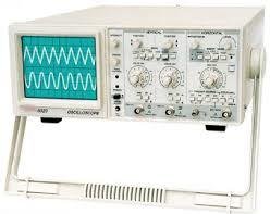
The cathode ray oscilloscope is an electrical test device used to produce waveforms in response to several input signals. It was originally known as an oscillograph. It is a development of the cathode ray tube. A standard cathode ray tube has the following parts:
- The electron gun
- A system of plates for deflecting the electron beam
- An evacuated strong glass envelope
- A fluorescent screen at one end of the glass envelope
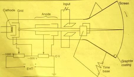
Inside the cathode ray oscilloscope, the main parts are as shown.
we now discuss each of the components making the CRO.
The electron gun
It is the component that supplies the electrons. After producing electrons, it accelerates them towards the screen and focus the beam to a point on the screen. The electron gun consists of :
- a heated cathode
- a grid to control electrons flow
- anodes to accelerate and focus the electron beam
Each of the above parts is maintained with a direct current potential from EHT source and a potential divider as shown.


The cathode is coated with thorium or strontium oxides which are usually preferred because they need a little energy to extract electrons from them.
The anodes are made of cylinders and discs maintained at high positive potential relative to the cathode so that they are able to attract the emitted electrons and direct them towards the screen.
Anodes as focusing beam
Focusing the cathode beam involves using two anodes that are at different potentials.
consider the diagram below:
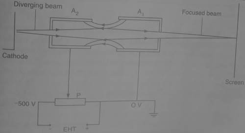
Anode A1 is at higher potential compared to anode A2. There is an electric field between the two anodes and there direction is such that to converge a diverging beam that is leaving the cathode through aperture of anode A1.
Electric field intensity increases when the potential difference between the two anodes A1 and A2. Increasing Electric field intensity increases the degree of focusing.
The potential difference is controlled by the potential divider P which is the focusing knob on the control panel.
The grid
In cathode ray oscilloscope, grid is a small hollow cylinder with a small hole at the end. Grid is used to control the intensity of the beam. The figure below shows cathode ray illustrated in a cathode ray tube.

The potential divider is used to make the grid more negative or less negative. Sliding it to the left increases it’s negative potential and sliding it to the right reduces the negative potential. When the grid is made less negative, more electrons are allowed to pass through it and when it is more negatives, fewer electrons are allowed to pass through.
Because Intensity of the spot on the screen is determined by the by the number of electrons striking the screen, grid is therefore used to control the intensity of the beam and hence brightness of the spot on the screen. The brightness knob controls the potential divider that varies the potential difference between the grid and the cathode. see the diagram below:

The deflection System
Deflection system is used to alter direction of the beam horizontally or vertically. If the deflection system is off or absent, the the beam will strike the screen at the center. The vertical deflection system causes the beam displaced up or down from the center of the screen. Horizontal deflection system displaces the beam on either sides of the center spot.
Vertical Deflection System
They causes the beam to deflect vertically across the screen when they are switched on. Vertical deflection system is also known as the Y-plates and their signal is usually fed in through the Y-Input terminal.
Consider the setup below:

When the switch is closed, Y1 is at positive potential while Y2 is at negative potential. The beam is therefore attracted towards plate Y1 and so the beam hits the screen at B.
If the polarity is changed such that Y2 is the positive one, the bright spot is observed at point C on the screen showing that the beam has bent towards Y2 . If There is a constant reversal of the polarities of the vertical deflection system, the spot on the screen keeps shifting from B to C to B at the frequency of the reversals.
Most often, an alternating current is connected to the vertical deflection system and so the spot is observed moving up and down in accordance with the frequency of the a.c voltage.
When the frequency of the a.c voltage is high, the persistence of vision makes the movement of the spot up and down looks like a vertical straight line on the screen. see the figure below:

The horizontal deflection system
They are also referred to as the X-plates as they cause the deflection of the spot to occur parallel to the X-axis.
consider the set up below:

When the plates are arranged as above, x1 is at positive potential and so the electron beam is deflected horizontally towards M. When The polarity are changed such that x2 is now the positive one, the beam is deflected towards N.
A varying voltage is applied to the X-plates from a special circuit known as the time base. The time base circuit causes movement of the bright spot in a constant speed from one end of the screen to the other. when It reaches the end, it disappears momentarily before it reappear again and move across.
The moment the spot is moving across the screen is known as the sweep. The moment it is disappearing from the screen is known as the flyback
Consider the figure below.
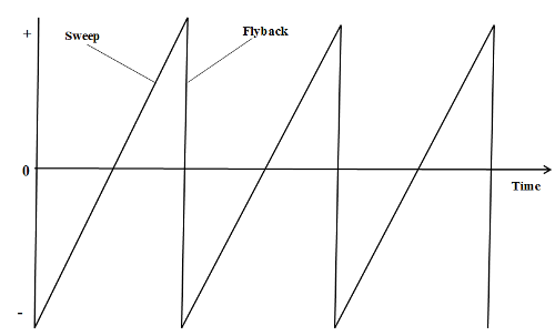
When the time base circuit is switched on, the voltage increases uniformly to peak (sweep) and then drops suddenly(flyback).
Increase of voltage causes the bright spot to move horizontally at a uniform speed until a peak voltage is reached. The time base voltage then drops suddenly to a maximum negative value causing the spot to fly back to the starting point at the other end of the screen. The voltage builds up again and the process is repeated in cycles.
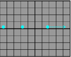
The movement of the spot across the screen(sweep) can be controlled by use of time base control knob which operates the frequency of the time base voltage. Increase of frequency results to reduction of sweep time. When the frequency is low, the spot moves slowly across the screen and can be followed by your eye as in the diagram below.
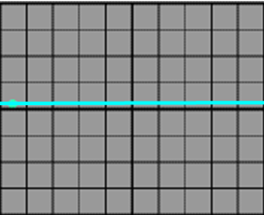
When frequency of the time base is high, the movement of spot traces a permanent horizontal line across the screen as shown below.
If input voltage at the y-plates and the time base voltages are switched on simultaneously, the spot is deflected vertically and horizontally at the same time causing a two dimensional movement in form of a sine curve on the screen. The figure below illustrates the Y-plates and time base circuit.

In the figure, we are shown the signal that would be formed when the two circuits are working simultaneously.
The CRO screen
It is usually coated with a fluorescent substance called phosphor. Phosphor, which is made from zinc sulphide glows when electrons collides with it. This glow persists for about 0.05 seconds and so the screen continues to glow even after the beam has passed the point of impact.
The persistent of the phosphor together with the persistent of vision in the eye enables the wave form to be observed on the screen. Inside of the tube is coated with graphite because of the following functions:
- conduction of the electrons to the earth
- shielding the beam from external electric fields
- Accelerating electrons towards the screen since it has the same potential as the anodes.
The following video shows how to use the cathode ray oscilloscope:
Leave a Reply