
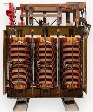
Electromagnetic induction is the phenomenon in which an electromotive force (e.m.f.) is produced whenever the magnetic flux linking a conductor changes. This principle, discovered by Michael Faraday in 1831, has transformed modern electrical engineering and led to the invention of devices that have become indispensable in everyday life. Among its many applications are the transformer, the moving-coil microphone, and the induction coil. Of these, the transformer stands out as one of the most significant because it makes efficient generation, transmission, and distribution of electrical energy possible.
Have you ever wondered how electricity generated at a power station reaches homes, schools, hospitals, and industries hundreds of kilometers away without losing most of its energy? Or why your phone charger can safely convert the 240 V mains supply into just a few volts for charging your device?
The answer lies in one of the most important applications of electromagnetic induction—the transformer.
What is a Transformer?
A transformer is an electrical device that transfers electrical energy from one circuit to another through the process of mutual induction. Unlike many electrical devices, a transformer has no moving parts, making it highly efficient and reliable.
It consists of two separate coils of insulated copper wire wound around a common laminated soft iron core:
- The primary coil, which is connected to an alternating current (AC) power source.
- The secondary coil, from which electrical energy is obtained.
When an alternating current flows through the primary coil, it produces a continuously changing magnetic field in the iron core. This changing magnetic field links the secondary coil, inducing an alternating e.m.f. across it according to Faraday’s Law of Electromagnetic Induction. Since the coils are electrically isolated but magnetically linked, energy is transferred without direct electrical contact.
Why Must a Transformer Use Alternating Current?
A transformer only works with alternating current (AC) because electromagnetic induction requires a changing magnetic field.
When direct current (DC) is supplied, the magnetic field remains constant after a brief moment, so no continuous e.m.f. is induced in the secondary coil. In contrast, AC continuously changes its magnitude and direction, creating a changing magnetic flux that induces a voltage in the secondary coil.
This explains why transformers are essential components of AC power systems but cannot operate normally on a steady DC supply.
Why Are Transformers So Important?
Modern civilization would be almost impossible without transformers. They allow electrical energy to be transmitted over long distances with minimal power loss by increasing the transmission voltage. Near consumers, transformers reduce the voltage to safe levels suitable for homes, schools, hospitals, and industries.
Transformers are found in countless applications, including:
- National electricity transmission and distribution networks.
- Phone and laptop chargers.
- Televisions and audio systems.
- Medical equipment.
- Industrial machines.
- Renewable energy systems such as solar and wind power installations.
Without transformers, electrical power transmission would be highly inefficient and extremely expensive.
Construction of a Simple Transformer
By the end of this chapter, you will understand not only how transformers work, but also why they are among the most important inventions in electrical engineering and modern technology.
The diagram below illustrates the basic parts of a transformer.

Main Components
1. Primary Coil
The primary coil receives electrical energy from an alternating current (AC) source.
As AC flows through the coil, the current continually changes direction, producing a continuously changing magnetic field.
2. Soft Iron Core
The soft iron core performs two important functions:
- It provides a closed magnetic path.
- It transfers almost all the magnetic flux produced by the primary coil to the secondary coil.
Soft iron is chosen because it:
- magnetizes easily,
- demagnetizes quickly,
- has low hysteresis loss.
3. Secondary Coil
The secondary coil is not directly connected to the primary circuit.
Instead, the changing magnetic flux passing through it induces an alternating e.m.f.
This induced voltage supplies electrical energy to the external circuit.
Principle of Operation
A transformer works according to Faraday’s Law of Electromagnetic Induction.
The sequence of events is as follows:
- Alternating current flows through the primary coil.
- A changing magnetic field is produced.
- The magnetic field passes through the soft iron core.
- The changing magnetic flux links the secondary coil.
- An alternating e.m.f. is induced in the secondary coil.
- If a load is connected, current flows in the secondary circuit.
Notice that there is no electrical connection between the two coils.
Energy is transferred entirely through the magnetic field.
Why Doesn’t a Transformer Work with Direct Current?
A transformer requires a changing magnetic field.
Alternating current continuously changes its direction and magnitude, producing a continuously changing magnetic flux.
Direct current behaves differently.
After the circuit is switched on, the current becomes constant.
A constant current produces a constant magnetic field.
Since the magnetic field no longer changes,
there is
- no changing magnetic flux,
- no induced e.m.f. in the secondary coil.
Therefore,
Transformers only operate with alternating current (AC).
Classroom Experiment
Aim
To determine how the induced secondary e.m.f. varies with the number of turns in the secondary coil.
Apparatus
- Long insulated copper wire
- Soft iron rod
- Low-frequency AC source
- AC voltmeter
- Electric bulb
- Switch
- Connecting wires
Experimental Setup
The apparatus is arranged as shown in the figure.

The primary coil is connected to the AC supply through switch K.
The secondary coil is connected to
- an AC voltmeter
- a small bulb.
Both coils are wound around the same soft iron rod.
This allows magnetic flux from the primary coil to pass efficiently through the secondary coil.
Procedure
- Wind 20 turns of insulated copper wire around the soft iron rod to form the primary coil.
- Wind another insulated copper wire to form the secondary coil with 10 turns. Ensure that the coils are wound close together.
ii. Connect. the primary coil to the low AC source, the secondary coil to the voltmeter and bulb.
iv. Close switch K.
v. observe
- the voltmeter reading,
- the brightness of the bulb.
vi. Increase the number of turns in the secondary coil while keeping the primary coil unchanged.
Record
- the voltmeter reading,
- the brightness of the bulb.
Repeat for several values of secondary turns.
Sample Results
| Primary Turns (Np) | Secondary Turns (Ns) | Secondary Voltage (Vs) | Bulb Brightness |
|---|---|---|---|
| 20 | 10 | Low | Dim |
| 20 | 20 | Equal to input | Normal |
| 20 | 30 | Higher | Bright |
| 20 | 40 | Much higher | Very bright |
Observation
As the number of turns in the secondary coil increases,
- the induced secondary e.m.f. increases,
- the bulb glows more brightly.
Explanation
Each turn of wire cuts the changing magnetic flux.
The more turns present,
the greater the total change in magnetic flux linkage.
Consequently,
a larger e.m.f. is induced.
This agrees with Faraday’s Law, which states that induced e.m.f. is proportional to the rate of change of magnetic flux linkage.
Mathematically,Flux linkage=NΦ
where
- is the number of turns,
- is the magnetic flux.
Increasing N increases the total flux linkage and therefore increases the induced voltage.
Relationship Between Voltage and Number of Turns
Experiments show that
the secondary voltage is directly proportional to the number of turns on the secondary coil.
The transformer equation is therefore
where
- = secondary voltage
- = primary voltage
- = number of turns on the secondary coil
- = number of turns on the primary coil
This equation applies to an ideal transformer, where no energy losses occur.
Types of Transformers
(i) Step-Up Transformer
A transformer is called a step-up transformer when
Since the secondary has more turns,
The output voltage is greater than the input voltage.
Current decreases correspondingly.
Applications include:
- electricity transmission
- X-ray machines
- television power supplies
Step-Down Transformer
A transformer is called a step-down transformer when
The secondary voltage becomes lower than the primary voltage.
Current increases correspondingly.
Applications include:
- mobile phone chargers
- laptop adapters
- doorbells
- household electronic devices
Practical Applications of Transformers
Transformers are found in nearly every electrical system. Some common applications include:
- National electricity transmission lines.
- Distribution substations.
- Mobile phone chargers.
- Laptop power adapters.
- Television sets.
- Audio amplifiers.
- Welding machines.
- Medical equipment.
- Renewable energy systems.
Transformer Equations
From the experiment carried out in the previous lesson, it was observed that increasing the number of turns in the secondary coil increases the induced secondary voltage. Careful experiments show that the ratio of the secondary voltage to the primary voltage is equal to the ratio of the number of turns on the two coils. This relationship is known as the turns rule.
For an ideal transformer;
where:
Vs = Secondary voltage
Vp = primary voltage
Ns = Number of turns on the secondary coil
Np = Number of turns on the primary coil
This equation is called the turns ratio equation and assumes that the transformer has negligible resistance and no energy losses.
Understanding the Turns Rule
The turns rule shows that the output voltage depends entirely on the ratio of the number of turns in the two coils.
- If the secondary coil has more turns than the primary coil, the output voltage becomes greater than the input voltage. Such a transformer is called a step-up transformer.
- If the secondary coil has fewer turns than the primary coil, the output voltage becomes less than the input voltage. Such a transformer is known as a step-down transformer.
- If both coils have the same number of turns, the output voltage is equal to the input voltage. This arrangement is called an isolation transformer.
Worked Example 1
A transformer has 250 turns on the primary coil and 1000 turns on the secondary coil. If the primary voltage is 24 V, determine the secondary voltage.
Solution
Using the turns ratio;
Therefore,
Answer: The secondary voltage is 96 V.
Electrical Power in a Transformer
Electrical power is the product of voltage and current.
For the primary coil,
For the secondary coil;
where:
Pin = Input power
pout = output power
Ip primary current
Is = secondary current
Transformer Efficiency
No transformer is perfectly efficient because some electrical energy is always lost as heat or magnetic losses.
The efficiency of a transformer is given by:
Since
and
then;
The Ideal Transformer
An ideal transformer is one that has no energy losses.
Therefore; Input power equals output power.
Hence;
Combining this equation with the turns rule gives another important transformer relationship;
This equation is one of the most useful relationships in transformer calculations.
Current in Step-Up and Step-Down Transformers
A common misconception among students is that both voltage and current increase simultaneously. This is not true.
For an ideal transformer, electrical power remains constant.
Consequently:
Step-Up Transformer
When the voltage increases,
- the current decreases.
Therefore,
Secondary voltage > Primary voltage
Secondary current < Primary current
Step-Down Transformer
When the voltage decreases,
- the current increases.
Therefore,
Secondary voltage < Primary voltage
Secondary current > Primary current
This explains why electricity is transmitted over long distances at very high voltages and relatively low currents. Lower current reduces the amount of energy lost as heat in transmission cables.
Worked Example 2
A transformer has an efficiency of 95%. If the input power is 500 W, calculate the output power.
Solution;
Using;
Substituting the values;
Hence; Answer: The output power is 475 W.
Energy Losses in a Transformer
Although transformers are highly efficient devices, they are not perfect. During operation, some of the electrical energy supplied to the primary coil is lost before it reaches the secondary coil. These losses reduce the transformer’s efficiency and produce unwanted heating.
There are four main causes of energy loss in a transformer:
- Flux leakage
- Copper (winding) losses
- Eddy current losses
- Hysteresis losses
Revision Exercise
Test Your Knowledge: Transformers
Answer the following questions based on transformer principles and equations.
1. Why can’t a transformer operate continuously when connected to a steady Direct Current (DC) supply?
2. In an ideal transformer, if the secondary coil has more turns than the primary coil (Ns > Np), what happens to the voltage and current?
3. A transformer has an efficiency of 95%. If the input power is 500 W, what is the output power?
Interactive Quiz: Transformers & Power Transmission
Answer the following 20 questions to test your complete understanding of transformer principles, equations, and applications.
1. Who discovered the principle of electromagnetic induction in 1831?
2. What process does a transformer use to transfer electrical energy between circuits?
3. Which component of a transformer is directly connected to the alternating current (AC) power source?
4. Why are transformer cores typically "laminated"?
5. Why must a transformer use alternating current (AC) instead of steady direct current (DC)?
6. What happens immediately after a steady DC supply is switched on to a transformer primary circuit?
7. Why is soft iron specifically chosen for making the transformer core?
8. In the classroom experiment, what happens to the secondary voltmeter reading as the number of turns in the secondary coil is increased?
9. Mathematically, what does the formula Flux Linkage = NΦ represent?
10. Which condition identifies a step-up transformer?
11. Which device uses a step-down transformer in daily household applications?
12. What is an isolation transformer?
13. A transformer has 250 primary turns and 1000 secondary turns. If the primary voltage is 24 V, what is the secondary voltage?
14. What is the formula for calculating the electrical input power (Pin) of a transformer?
15. In an ideal transformer, what is the relationship between input power and output power?
16. Why is electricity transmitted over long distances at very high voltages?
17. Energy lost due to the electrical resistance within the copper wire coils is known as what?
18. What is "flux leakage" in a transformer?
19. Energy lost due to the continuous reversal of magnetic domains in the iron core is called:
20. If a transformer has an output power of 475 W and an input power of 500 W, what is its percentage efficiency?
Related topics