
Drawing ray diagrams for thin lenses involves representing image formations by light rays in books. We use ray diagrams to represent images formed by thin lenses. Ray diagrams are straight lines with arrows that shows direction of light rays.
Points to note when drawing ray diagrams
- we represent real rays and real images using solid lines.
- we represent virtual rays and virtual images using broken lines.
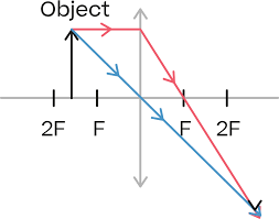
- To locate the image, we draw two of the three important rays known to intersect at a point from the tip of the object towards the lens.
- The first ray parallel to principal axis and through principal focus.
- The second ray from the tip of the object, through the optical center.
- Third that passes through the principal focus that moves parallel to the principal axis after refraction.
- Where two or more rays intersect after refraction by the lenses is the tip of the image.
- if the object stands and is perpendicular to the principal axis, the image is also perpendicular to the principal axis.
- To complete the image, draw perpendicular a line to the principal axis from the tip of the image.
- If the foot of the object crosses the principal axis, we should draw two of the three rays used to locate image for both the tip and the foot of the object.
- A point object for the image tip should be joined with point image of the foot to get the desired image.
- We represent converging lenses using the following symbol:
Representing lenses in ray diagrams
To show concave and convex lenses in ray diagrams involving thin lenses, we use following symbols.

We represent concave lenses using the symbol below.

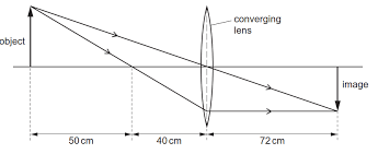
Example problem
A Physics students places an object that is 15cm tall 32cm from a concave lens of focal length 20 cm. By scale drawing, determine:
(a) The position of the image formed
(b) Magnification of the image
(c) The height of the image
solution
We use the scale of 1 cm to represent 5 cm and using two rays to form an image, the resultant image after reflection is as shown

(a) From the diagram, one can see that the image is formed 52cm from the lense.
(b) From the diagram, the height of the image from the principal axis is 24 cm.

substituting for the values of hi and ho, we have:
Magnification has no unit as it is a ratio.
The same result could be obtained by finding ration of image distance to object distance with some slight variation that comes with measurement errors:
(c ) From the scale diagram, the height of the image is about 24.5cm
Remarks:
After drawing ray diagrams for thin lenses, we can get further insights about the image formed. The image upside down but is formed by two rays actually meeting at a point, hence the image is real.
Note that the image is taller than the object, hence it is magnified just by looking.
Practice Question:
- An object 24cm high is placed 25cm from a converging lens of focal length 30cm. By scale drawing, find the position, size and nature of the image.
- An object 20cm high is placed 15cm from diverging lens of focal length 20cm. Find using graphical construction, the position, size and nature of the image formed by such lens.
Related Topics
- Introduction to Thin lenses
- Terms used in thin lenses
- 1 method to determine Focal length from lens formula
- Deriving the lens formula
- Understanding the language of Thin Lens
- Focal length by non-parallax method
- Estimating focal length
- focusing a distance object
- The lens formula
- Linear magnification
- Image formation by thin lenses
- Introduction to thin lenses
Leave a Reply to Focal length from lens formula – precisestudy Cancel reply