The direction of the induced current is determined by Lenz’s Law. When a conductor or coil experiences a change in magnetic flux, an electromotive force (emf) is induced in it. This phenomenon is explained by Faraday’s Law of Electromagnetic Induction. However, Faraday’s Law does not indicate the direction of the induced current.
Lenz’s Law states that the induced current always flows in such a direction that the magnetic field produced by it opposes the change causing it.
In this experiment, a centre-zero galvanometer is first used to establish the relationship between the direction of current flow and the direction of galvanometer deflection. This relationship is then applied when studying induced currents in coils and magnets.
Experiment To Determine the Direction of the Induced Current in a Coil
Apparatus
- Sensitive centre-zero galvanometer
- Variable resistor (rheostat)
- Dry cell
- Switch
- Connecting wires
Aim
To establish the direction of galvanometer deflection with respect to the direction of current flow.
Theory
Before studying induced currents, it is necessary to know which direction of galvanometer deflection corresponds to a particular direction of current flow.
The circuit shown consists of a battery, a rheostat, a switch and a sensitive centre-zero galvanometer connected in series.
When current flows from A to B, the galvanometer needle deflects in a particular direction. If the current is reversed and flows from B to A, the galvanometer deflects in the opposite direction.
This calibration enables the galvanometer to be used later in electromagnetic induction experiments.
Procedure
- Set up the circuit as shown in the figure.

- Adjust the variable resistor to a high resistance value.
- Ensure that the switch is open.
- Close the switch briefly.
- Observe the direction of galvanometer deflection when current flows from A to B.
- Reverse the battery terminals.
- Close the switch again.
- Observe the new direction of galvanometer deflection.
- Record your observations.
Observations
| Direction of Current | Galvanometer Deflection |
|---|---|
| A → B | Needle deflects to the right |
| B → A | Needle deflects to the left |
Conclusion
The direction of galvanometer deflection depends on the direction of current flow.
This information can now be used to determine the direction of induced current when a magnet moves towards or away from a coil.
Virtual Laboratory Simulation
Investigating the Direction of Induced Current in a Coil
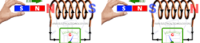
When a magnet moves relative to a coil, an electric current is induced in the coil. The direction of this current depends on whether the magnet is approaching or moving away from the coil. This simple experiment helps us understand the relationship between magnetic motion and induced current.
Procedure
- Connect a sensitive galvanometer to a coil as shown in the experimental setup.
- Move the north pole of a bar magnet toward the coil and observe the direction of the galvanometer’s deflection.
- Next, move the magnet away from the coil and again note the direction of the pointer’s movement.
Observation
When the north pole of the magnet is moved toward the coil, the galvanometer pointer deflects to the left. This indicates that an induced current is flowing through the circuit in the direction D → C → B → A. see the figure below

When the north pole is moved away from the coil, the pointer deflects to the right. This shows that the induced current now flows in the opposite direction, D → A → B → C.

Explanation
As the north pole of the magnet approaches the coil, the magnetic flux linked with the coil increases. An induced current is therefore produced in the coil. The direction of this current is such that the coil behaves like an electromagnet with its north pole formed at the end nearest to the incoming magnet.
The induced north pole repels the approaching north pole of the magnet. In this way, the induced magnetic field opposes the change that produces it.
When the magnet is moved away from the coil, the magnetic flux through the coil decreases. The induced current reverses its direction, causing the end of the coil nearest the magnet to become a south pole. This south pole attracts the receding north pole of the magnet.
Again, the induced magnetic field acts to oppose the change in magnetic flux. This behavior is consistent with Lenz’s Law, which states that the induced current always flows in a direction that opposes the cause producing it.
Direction of Induced Current in a Straight Conductor
Lenz’s law can also be used to determine the direction of induced current in a straight conductor moving through a magnetic field. Consider a conductor AB placed between the poles of a strong U-shaped magnet as shown in below.

When the conductor is moved across the magnetic field, it cuts the magnetic lines of force and an e.m.f. is induced in it.
As the conductor is moved upwards, the magnetic flux linked with the conductor changes. According to Lenz’s law, the induced current flows in such a direction that the magnetic effect produced opposes the upward motion. It is observed that the current flows from B to A as shown. The

The induced magnetic field therefore acts to oppose the motion responsible for its production.
When the conductor is moved downwards, the change in magnetic flux occurs in the opposite direction. Consequently, the induced current reverses and flows from A to B as shown.

The magnetic field produced by this current opposes the downward motion of the conductor.
This experiment demonstrates an important feature of electromagnetic induction: whenever the direction of motion is reversed, the direction of the induced current also reverses. The induced current is always such that its magnetic effect opposes the change that produces it.
The opposition predicted by Lenz’s law is a direct consequence of the principle of conservation of energy. Mechanical work must be done to move the conductor through the magnetic field. This mechanical energy is converted into electrical energy in the conductor. If the induced current aided the motion instead of opposing it, energy would be produced without any external work being done, which would violate the law of conservation of energy.
The direction of the induced current may also be determined using Fleming’s Right-Hand Rule. The forefinger is pointed in the direction of the magnetic field, the thumb in the direction of motion of the conductor, and the middle finger then indicates the direction of the induced current. The direction obtained using Fleming’s rule is always consistent with Lenz’s law.
Interactive Simulation: Lenz’s Law in a Moving Conductor
The following simulation is designed for direct embedding in a WordPress Custom HTML block. It demonstrates a conductor moving vertically through a magnetic field between the poles of a U-shaped magnet. The induced current direction changes automatically according to Lenz’s law.
Electromagnetic Induction: Moving Conductor AB
Motion: Stationary
Current: None
Galvanometer: 0
What Is Fleming's Right-Hand Rule?
Fleming's Right-Hand Rule is used to determine the direction of induced current in a conductor moving within a magnetic field. It is a simple yet powerful tool used to determine the direction of induced current in a conductor moving through a magnetic field. Based on the principles of electromagnetic induction, the rule has practical applications in generators, renewable energy systems, and science education. By relating the directions of motion, magnetic field, and current, it helps explain one of the most important processes in modern electrical technology.
Fleming's Right-hand rule states that:
If the thumb and the first two fingers of the right hand are held mutually at right angles with the first finger pointing in the direction of the field, thumb pointing in the direction of motion, then the second finger points in the direction of the induced current.
The rule is mainly applied in electric generators, where mechanical energy is converted into electrical energy.
To use the rule, the thumb, forefinger, and middle finger of the right hand are held at right angles to one another.

Each finger represents a different quantity:
- Thumb – Direction of motion of the conductor.
- Forefinger – Direction of the magnetic field (from north to south).
- Middle finger – Direction of the induced current.
When these three fingers are positioned correctly, the middle finger points in the direction of the current generated in the conductor. From the diagram above part b, Fleming's right rule predicts that the induced currents flows from X to Y. The current must flow in the direction X-Y in order to produce a force to the left opposing the motion to the right.
Example 1
A square loop of a conductor is pulled at a steady speed across a uniform magnetic field as in figure below.

(a) Determine in the figure the direction of induced current in the sides AB, AD, CD and BC, if any.
(b) Explain what happens when:
(i) all the sides are moving in the uniform field and state the potential difference across points AB.
(ii) the side CD leaves the field.
(c) Suggest why in the absence of friction, more force is required to keep the coil moving at a steady speed when side CD leaves the field.
solution
(a)
Sides AD and BC have no induced e.m.f. and hence no induced current, since they are not cutting the magnetic field. Sides AB and CD cut the magnetic field, causing current to flow from B to A in AB and C to D in CD.
(b)
(i) The currents in AB and CD are equal in magnitude and opposite each other. The resultant potential difference across the points A and B is zero.
(ii) Induced e.m.f. in AB sets up a current that takes the path A → D → C → B → A. There is no induced current in side CD.
(c)
The flow of current in AB creates a force that tends to oppose the motion.
Fleming's right hand rule which is also known as dynamo rule is in agreement with the Lenz's law.
The Science Behind the Rule
Fleming's Right-Hand Rule is based on the principle of electromagnetic induction discovered by Michael Faraday in 1831. Faraday found that when a conductor moves through a magnetic field, an electromotive force (EMF) is induced in it. This phenomenon is known as electromagnetic induction.
The induced current flows because the moving conductor cuts across magnetic field lines. The direction of this current depends on both the direction of motion and the direction of the magnetic field. Fleming's Right-Hand Rule provides a simple method for determining this direction without complex calculations.
Related topics
- Factors affecting magnitude of the induced e.m.f
- Hans Oersted
- phases in waves
- Calculus Integration
- Induced Electromotive force
- Magnetic effect to an electric current
References
Faraday, M. (1831). Experimental Researches in Electricity. London: Royal Society.
Fleming, J. A. (1902). The Alternate Current Transformer in Theory and Practice. London: Electrician Printing and Publishing Company.
Halliday, D., Resnick, R., & Walker, J. (2018). Fundamentals of Physics (11th ed.). Hoboken, NJ: Wiley.
Serway, R. A., & Jewett, J. W. (2019). Physics for Scientists and Engineers (10th ed.). Boston, MA: Cengage Learning.
KLB (2013) Secondary Physics book 4 (3rd ed.), Kenya Literature bureau.
Comments
2 responses to “Lenz’s law: Direction of the induced current”
[…] Direction of induced current […]
[…] The lenz’s law […]