Category: Physics

  • High Voltage Power Transmission and Power Losses

    High Voltage Power Transmission and Power Losses

    High voltage power transmission systems are designed to transport electrical power over long distances while reducing power losses caused by resistance in transmission cables. By increasing voltage and lowering current, power companies can deliver electricity more efficiently, safely, and reliably. This process plays a major role in modern power grids and helps ensure stable electricity supply across cities and rural areas.

    In this article, you will learn how high voltage power transmission works, why power losses occur during transmission, the importance of transformers in reducing energy wastage, and the dangers associated with high voltage lines. You will also explore practical examples and calculations that explain how electrical engineers minimize power loss in transmission systems.

    Whether you are a physics student, engineering learner, teacher, or simply curious about electricity transmission, this guide will help you clearly understand the science behind high voltage power transmission and power losses.

    Electricity generated at power stations must travel long distances before it reaches homes, industries, schools, and businesses. To make this possible efficiently, electrical power is transmitted using high voltage transmission lines. High voltage transmission helps reduce energy losses and ensures reliable delivery of electricity over large distances.

    High voltage power transmission flow diagram
    • Electricity is generated at power stations.
    • Voltage is stepped up for efficient long-distance transmission.
    • High voltage reduces power losses in transmission cables.
    • Substations step the voltage down before distribution to consumers such as homes, industries, schools, and businesses.

    What is High Voltage Transmission?

    High voltage transmission is the process of carrying electrical power over long distances using very high voltages such as 110 kV, 220 kV, 400 kV, or even 765 kV. Transmitting electricity at high voltage reduces the amount of energy lost as heat in the transmission cables.

    Power stations usually generate alternating current (AC) electricity at voltages between 11 kV and 25 kV. Before the electricity is transmitted, transformers are used to step up the voltage to much higher levels, typically between 132 kV and 400 kV.

    The electricity is then transmitted through overhead power lines to substations, where the voltage is stepped down for safe distribution to consumers.

    Different consumers require different voltage levels:

    • Heavy industries may require voltages above 30 kV
    • Light industries may use around 10 kV
    • Homes and domestic users usually require 240 V
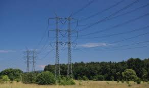
    High voltage power transmission cables
    power transmission cables

    How Power is Distributed

    The transmission and distribution process follows these stages:

    1. Electricity is generated at the power station.
    2. A transformer steps up the voltage for long-distance transmission.
    3. Electricity travels through high voltage transmission cables.
    4. Substations step down the voltage.
    5. Electricity is distributed to homes, industries, and businesses at suitable voltage levels.

    Why High Voltage Reduces Power Loss

    Electrical cables have resistance, and this resistance causes some electrical energy to be lost as heat during transmission.

    The power loss in transmission lines is given by:

    P=I2RP = I^2RP=I2R

    Where:

    • P = power loss
    • I = current flowing through the cable
    • R = resistance of the cable

    From the formula, power loss increases when current increases. Therefore, reducing current reduces energy losses.

    Since electrical power is also given by:

    P=VIP = VI

    For the same amount of power, increasing the voltage allows the current to decrease. This is why electricity is transmitted at very high voltages and low currents.

    Methods Used to Reduce Power Losses

    Power companies use several methods to minimize losses during transmission:

    1. Stepping Up Voltage

    Transformers increase the voltage before transmission. Higher voltage means lower current and therefore lower power loss.

    2. Using Thick Transmission Cables

    Thicker cables have lower resistance, which reduces heat losses.

    3. Using Good Conductors

    Transmission cables are made using materials with low electrical resistance.

    Why Aluminum is Preferred for Transmission Cables

    Aluminum is commonly used in transmission lines because:

    • It is a good conductor of electricity
    • It is lightweight
    • It is cheaper than many other conducting materials

    Dangers of High Voltage Transmission

    Although high voltage transmission is efficient, it also presents several risks:

    • Electric shock if cables fall or hang too low
    • Fires caused by loose or damaged cables
    • Strong electric fields that may affect nearby communities
    • Lightning strikes causing surges in electrical systems
    • Cables touching during strong winds and causing sparks or fires

    Proper maintenance and safety measures are therefore very important.


    Example Problem

    A transmission cable has a resistance of 100 Ω and carries electricity at 10 kV with a current of 1.0 A. The voltage is stepped up to 18 kV using a transformer.

    Determine the power loss after stepping up the voltage.

    Solution

    Assuming the transformer is 100% efficient:

    Step 1: Use the transformer power relationship

    VpIp=VsIsV_p I_p = V_s I_sVp​Ip​=Vs​Is​

    Substituting the values:

    • Primary voltage = 10,000 V
    • Primary current = 1.0 A
    • Secondary voltage = 18,000 V

    10000×1.0=18000×Is10000 \times 1.0 = 18000 \times I_s10000×1.0=18000×Is​ Is=1000018000I_s = \frac{10000}{18000}Is​=1800010000​ Is=0.556 AI_s = 0.556\ AIs​=0.556 A

    Step 2: Calculate Power Loss

    Using:P=I2RP = I^2RP=I2R P=(0.556)2×100P = (0.556)^2 \times 100P=(0.556)2×100 P30.9 WP \approx 30.9\ WP≈30.9 W

    Without Stepping Up the Voltage

    P=(1.0)2×100P = (1.0)^2 \times 100P=(1.0)2×100 P=100 WP = 100\ WP=100 W

    This shows that stepping up the voltage significantly reduces power loss.


    Practice Question

    A generator produces 750 kW at a voltage of 15 kV. The voltage is stepped up to 125 kV and transmitted through cables with a resistance of 500 Ω.

    Assuming the transformers are 100% efficient, calculate:

    1. The current produced by the generator
    2. The current flowing through the transmission cables
    3. The voltage drop across the cables
    4. The power lost during transmission
    5. The power reaching the substation

    Conclusion

    High voltage transmission is an essential part of modern electrical power systems. By transmitting electricity at high voltage and low current, power companies minimize energy losses and improve efficiency over long distances.

    Transformers play a key role in stepping voltage up for transmission and stepping it down for safe use by consumers. Despite the dangers associated with high voltage lines, proper design and maintenance make power transmission both efficient and reliable.

    Related topics

  • Exam questions on current and electricity

    Exam questions on current and electricity

    Current and electricity are core topics in physics, encompassing electric current, circuits, resistance, and the behavior of electrons. Key areas that can be tested include the nature of electric current. Another key area is Ohm’s law, Series and parallel circuits, the heating effect of electric current among others

    Questions

    1. Figure 1 shows four identical bulbs connected to a 15 volt battery whose internal is negligible.
    Diagram for Exam questions on current and electricity. Question one
    Figure 1

    Determine the reading of the voltmeter V. (2 marks).

    2. Figure 14 shows a circuit in which a battery. a switch , a bulb, resistor P, a variable resistor Q. a voltmeter V and two ammeters A1 and A2 of negligible resistance are connected.

    P has a resistance of 10 Ω. When the switch is closed A1 and A2 reads 0.10 A and the voltmeter reads 1.5 V.

    (a) Determine;. 
    (i) the current passing through P; (3 marks).

    (ii) the resistance of the bulb (2 marks).

    (b) The variable resistor Q is now adjusted so that a larger current flows through A2 .
    (i) State how this will affect the resistance of the bulb (1 mark)


    (ii) Explain your answer in (b)(i). (3 marks)


    (c) A house has one 100W bulb, two 60W bulbs and one 30W bulb. Determine the cost of having all the bulbs switched on for 70 hours,. given that the cost of electricity is 40 cents per kilowatt hour. (3 marks).
    • 3. (a) Define current stating its S.I units.               (2 mark)
     (b) A battery circulates charges round a circuit for 1.5 minutes. If the current is held at 2.5 Amperes,   what quantity of charge passes though the wire? (2 marks)


    4. Figure 2 shows arrangement of three capacities of 10µF, 2µF and 5µF.

     network three capacities of 10µF, 2µF and 5µF and a cell of 2V

    Determine the effective capacitance. (3 marks)

    5.(a) Figure 8 shows a graph of potential difference V (volts) against a current I(amperes) for a certain device.

    From the graph:

    (i) State with a reason whether or not the device obeys ohms law.    (2 marks)

    (ii) determine the resistance of the device at ;

         (I) I =1.5 A           (2 marks)

          (II) I = 3.5 A         (2 marks)

    (iii) From the results obtained in (ii) state how the resistance of the device varies as the current increases.      ( 1 mark)

    (iv) State the cause of this variation in resistance.  (1 mark)

    5(b) Three identical dry cells each of e.m.f 1.6 V are connected in series to a resistor of  11.4 ohms.  A current of 0.32A flows in the circuit. Determine:

       (i) The total e.m.f of the cells     (1 mark)

      (ii) The internal resistance of each cell;    (3 marks)

    6. Figure 6 below shows an electric generator. The points P and Q are connected to a cathode ray oscilloscope (CRO).

    exam question on electric generator:
    Figure 6

    Sketch on the axes provided the graph of the voltage output as seen on the CRO, given that when t=0 the coil is at the position shown in the figure.   (2 marks).

    7. A 60 W bulb is used continuously for 36 hours. Determine the energy consumed. Give your answer in kilowatt hour (kWh).  (3 marks)

    8. Figure 8 shows the cross-section of a dry cell. Use the information on the figure to answer questions 4 and 5.

    Figure 8

    Name the parts labelled A and B. (2 marks)

    8 (b)  State the use of the manganese(IV) oxide in the cell. (1 mark).

    9. A 4 ohms resistor is connected in series to a battery of e.m.f 6.0 V and negligible internal . Determine the power dissipated by the resistor (2 marks)

    10. State the reason why electrical power is transmitted over long distances at very high voltages .(1 mark)

    Related pages

  • Electric current and potential difference

    Electric current and potential difference

    Electric current and potential difference represents two phenomenon that depends on each other to exist in electricity concepts. An electric current is the rate of flow of charge through a conductor. Current flows when there is a potential difference between two points in a conductor. Electric current is measured in amperes by an instrument called ammeter. An ammeter is an electrical instrument used to measure the current flowing through a circuit. The ammeter is designed to be connected in series with the circuit. This ensures that the current flows through the ammeter, allowing it to accurately measure the amount of electrical current.

    There are two types of ammeters:

    Instruments used in experiments of electric current and potential difference

    • Analog Ammeter: This uses a needle or pointer to indicate the current on a scale.

    The figure below shows an analog ammeter ammeter common in school laboratories.

    An ammeter to measure Electric current
    An ammeter

    2. Digital Ammeter: This displays the current measurement on a digital screen. It provides a digital readout of the electrical current. Digital ammeter allows one to choose a scale of measurement in amperes (A), milli-amperes (mA), or micro-amperes (µA). It uses a numerical display rather than a moving needle or pointer.

    A Digital ammeter

    Electric current flows between two points in a closed path due to a potential difference between those two points. Sometimes the flowing current can be too small to me measured by an ammeter. A more sensitive instrument may therefore be required to measure small currents.

    A millimeter is an instrument used to measure current in terms of one in thousand of an ampere. A milliammeter measures current in terms of milli-amperes.

    $$1 \ milli-ampere(MA) = \frac{1}{1000} Amperes$$

    Much smaller currents can be measured by a micro- ammeter. A micro-ammeter measures current in terms of micro-ampere.

    $$1 \ micro-ampere(\mu A)= \frac{1}{1000000} \ amperes $$

    experiments of electric current and potential difference: A micro-ammeter to measure very small electric currents and a milli-ammeter to measure relatively small currents.
    A micro-ammeter

    Using an ammeter in measuring electric current

    An ammeter has very low electrical resistance. Therefore it is connected in series with the instrument whose current passing through need to be measured. When connecting an ammeter in the circuit, ensure it is done correctly. The correct procedure is such that current enters the ammeter through positive terminal and exits through the negative terminal. If connected such that convectional current enters through negative terminal, the ammeter may get damaged.

    The figure below shows the ammeter connected in series with the bulb. The convectional current flowing through the bulb also flows through the ammeter.

    Ammeter connected in series with a bulb in experiments of electric current and potential difference
    correct ammeter connection

    The figure below shows wrong ammeter connection. Note that the positive terminal of the ammeter is connected to the negative terminal of the cell.

    wrong ammeter connection

    Before connecting the ammeter in a circuit, confirm that it’s pointer is at zero mark on the scale. Otherwise, use the zero adjusting screw to move it to the correct position. Most of ammeters has two scales. An appropriate scale should be selected to safeguard the coil from damaged if current passing exceeds its capacity. For example an ammeter can have a scale of (0-3)A or (0-5)A. The figure below shows an ammeter dashboard with two scales; (0-5)A and (0-2.5)A.

    Ammeter reading with two scales

    If a scale of (0 – 5) A is selected, the meter can read up to 5 A. With such a scale, 10 divisions represents 1.0 A. For a (0-2.5) A scale, ten divisions will represent 0.5 A meaning each division is 0.05 A. From the diagram, the reading on the ammeter is 2.45 A while reading (0-5) A or 1.225 while reading the (0 -2.5) A.

    Electric current and potential difference: using a voltmeter

    while investigating electric current and potential difference, we need to measure potential difference across various components in the circuit. A voltmeter is always connected across the device (parallel to the device) which the voltage is to be measured. The figure below shows voltmeter connected across the bulb in parallel arrangement.

    circuit diagrams showing how to connect voltmeter while measuring potential difference across the bulb

    Voltmeter is connected in series because it is an instrument with high resistance to the flow of current. Therefore, It takes no current from the component across which the voltage is to be measured.

    The positive terminal of the voltmeter is connected to the point where convectional current is entering a component. Its negative terminal is connected to the point where the current is leaving the component.

    One should ensure that the pointer is exactly on the zero mark before connecting the voltmeter. If pointer is not at zero, the pointer should be adjusted to zero by the screw.

    potential difference

    Work must be done to move an electric charge through a conductor. The device that produces energy to do this work is called a source of electromotive force (e.m.f). The source may be a battery, which converts chemical energy to electrical energy, or a generator, which converts mechanical energy to electrical energy. When the battery does the work of pumping charges through a conductor or an electrical device, an electrical potential difference(p.d) develops between its end. This potential difference is measured in volts using the voltmeter.

    Potential Difference and the Voltmeter

    A lack of “pumping” charges through a conductor indicates that there is no potential difference between two points. The potential difference (p.d) between two points A and B (Vab)of a conductor is defined as the work done in moving a unit charge from point B to A.

    in other words:

    $$\text{Potential difference} = \frac{\text{work done W(in joules)}}{\text{charge moved Q (in coulombs)}}$$
    $$V_{AB} = \frac{W}{Q}$$

    where: (VAB) = potential difference across AB.

    • (W) = work done (in joules)
    • (Q) = charge moved (in coulombs)

    From the equation, one volt is equal to one joule per coulomb.

    Measuring potential difference

    The voltmeter measures potential difference. In laboratories, moving coil voltmeters are commonly used, although today many of these instruments are replaced by digital voltmeters.

    (a) Analogue voltmeter
    (b) Digital voltmeter

    Please note that instruments like fuel gauge and speedometers are essentially voltmeters.

    Example

    In moving a charge of 10 coulombs from point B to point A, 120 joules of work is done. What is the potential difference between A and B?

    solution:

    $$p.d = \frac{W}{Q} = \frac{120}{10} = 12V$$

    Using a Voltmeter

    A voltmeter is always connected across (in parallel to) the device whose voltage is to be measured. consider the diagram below.

    Voltmeter connected across the bulb
    lab setup for bulb connected across the battery

    Because the voltmeter has a high resistance to the flow of current, it draws very little current from the component.

    The positive terminal of the voltmeter is connected to the point where conventional current enters the component, while the negative terminal is connected to the point where the current leaves the component.


    Experiment To Investigate the Current and Voltage in a Parallel Circuit Arrangement

    Apparatus

    • Two 1.5 V cells
    • 3 identical bulbs
    • 3 ammeters
    • 4 voltmeters
    • Switch
    • Connecting wires

    Procedure

    • Connect the circuit as shown in figure below.
    Current and Voltage in Parallel
    • Switch on the circuit and take the readings on the ammeters A1, A2,A3 and A4.
    • Switch off the circuit and disconnect the ammeters.
    • Connect the bulbs and the voltmeters as shown in figure
    • Take the readings on V1,V2,V3 and V4.

    Observation

    1. Reading on A1 = Reading on A2 + Reading on A3 = Reading on A4
    2. Reading on V1 = Reading on V2 = Reading on V3 = Reading on V4.

    Conclusion

    When components are connected in parallel:

    1. The sum of the currents in parallel circuits is equal to the total current. The total current entering a junction equals the total current flowing out.
    2. The same voltage drops across each of the components.

    Example 2

    Find the current passing through L1 in figure below, given that 0.8 A passes through the battery, 0.28 A through L2, and 0.15 A through L3.

    Solution

    Current through battery = Current through L1 + Current through L2 + Current through L3

    0.8 = I1+I2+I3

    0.8=I1 + 0.28+0.15

    0.8 =I1 + 0.43

    Therefore:

    I1 = 0.8A – 0.43A = 0.37A

    Experiment To Investigate Current and Voltage in Series Arrangement

    Apparatus

    • 4 voltmeters
    • 3 torch bulbs (2.8 V)
    • Bulb holder
    • Switch
    • Connecting wires
    • Two cells

    Procedure

    • Connect the circuit as shown in figure below
    bulbs in series
    • Switch on the circuit and record the readings on the meters.
    • Switch off the circuit and disconnect the ammeter.
    • Connect the bulbs, ammeter, and voltmeters as shown in figure below.
    • Switch on the circuit and record the readings on the meters.
    observations

    The reading of current by the ammeters A1 and A2 and A3 is the same.

    The total voltage drops across the bulbs (V1+v2+v3) equals to the total voltage v4 across the terminals of the battery.

    please note that the observations will remain true even when the bulbs are not identical.

    conclusions

    In a series arrangement, the same current flows through each component.

    The sum of the voltage drops across the components is equal to supply voltage


    Summary

    • A voltmeter measures potential difference.
    • Potential difference is the work done per unit charge.
    • Voltmeters are connected in parallel across components.
    • In parallel circuits, current splits while voltage remains the same.
    • In series circuits, current remains the same throughout the circuit.

    Related Topics


  • Examination Questions on measurements

    Examination Questions on measurements

    Examination questions on measurements basically covers concepts like:

    •  Length and Distance
    • Weight and Mass
    • Basic Units and Conversions
    •  Volume and Capacity
    • Time
    • Temperature
    • Derived Units and Calculations
    •  Measuring Instruments
    • Precision and Accuracy

    Here are the questions that involves measurements

    1. The diagram below shows a piece of wood whose length is being measured using a strip of           measuring tape.


                What is the length of the piece of wood.

    2. Figure 1 below shows a Vernier calipers being used to measure the thickness of an object. It has a error of +0.01 cm.

    What is the correct measurement?                                                                       (2 marks)

    3. Figure  below shows  Perspex  container  with a square base  of side  5 cm . It is carrying  water  to a height  of 7 cm.

    When pebble is immersed  into  the water, the level  rise  to 10 cm. what is  the volume of the pebble? (2 marks)

    4.   A  drop  of  oil volume  6 x 10 -9 m3 forms  a patch  of area  0.0755 m2  on a water  surface. Estimate the of an oil  molecule ( 2 marks).

    Related topics

  • Trigonometric ratios:-Table of tangents

    Trigonometric ratios:-Table of tangents

    The table of tangents holds values for every acute angle from 0o to 90o. Each angle has a unique tangent ratio. We get this ratio when two lines meet to make the angle.

    Every combination of opposite and adjacent lines that makes a right angled triangle has a unique angle which they make.

    If we know the acute angle in a right angled triangle, we can use tables of tangents. This helps us find its corresponding tangent ratio. Similarly, if we know the angle and just one side, we can find the angle’s ratio. Then, we use the tangent relationship to find the other side.

    The table of tangents consists of angles from 0o to 90o. We express these angles in 4 significant figures and record their values in a table. All we need to do as mathematician is get a certain angle and find it’s corresponding ratio from the tables.

    We expresses angles in the table of tangents in degrees, points of degrees and as well as in minutes. 1 degree (1o) is equivalent to 60 minutes(60′).

    We have divided the table of tangents into three major columns as shown in the table extract below:

    The first column represents whole number degrees from 0o to 90o  and has column head labeled xo which represents

    The second column consists of 0.0o to 0.9o which divides a degree into 10 smaller units hence giving an accuracy of 0.1o.

    The third column is the one we have labeled ADD and it provides the second decimal value of the angle. Using the table of tangents, we can find angles u to second decimal places.

    Example

    Determine the tangent of 36.57o

    solution

    In the column labelled xo , look for the row headed 36 and then move along this row until you reach 0.5. The number at the intersection of 36 and 0.5 is 0.7400

    note that the number is recorded as 7400 and not 0.7400. This is done to save on space but you should check the first column after 36, That is, column headed 0.0, whatever value that is stated on that row in that column should be used as the starting value for all the columns in that row.

    so tan 36.5 =0.7400, to get the value for tan 36.57, we go to the add column and check on the column 0.07 and add it’s value on the far right of our previous value we read from the table. In this case it is 19 and should be read as 0.0019

    hence tan 36.57 should be 0.7400+0.0019 = 0.7419

    Example

    Use tables to find the tangent of 77o48′

    solution

    1o=60′, hence 48′ = (48′ x 1o)/60′ = 0.8o

    then 77o48′ can be expressed as 77.8o

    From the tables, you identify row 77 at xo column then move up to to the column 0.8 and read off that value at the intersection. This value is 0.6252 hence tan 77o48′ = tan 77.8o = 0.6252

    Example

    Find angle θ and α in the figure below.

    Related Topics


  • Exam questions on waves

    Here are exam questions on waves that are common in national exams.

    1. State two differences between electromagnetic waves and mechanical waves (2 marks)
    2. Figure 3 show straight waves incident on a divergent lens placed in a ripple tank to reduce its depth.
    showing exam question diagram on refraction of waves

    Complete the diagram to show the waves in both the shallow region and beyond the lens (2 marks)

    3. A ship in an ocean sends out an ultra sound whose echo is received after 3 seconds. if the wavelength of the ultra sound in water is 7.5 cm and the frequency of the transmitter is 20 kHz, determine the depth of the ocean. (3 marks)

    4. Explain the fact that radiant heat from the sun penetrates a glass sheet while radian heat from burning wood is cut off by the glass sheet. (2 marks)

    Question 5

    5. (a) figure 5 shows a displacement-time graph for a progressive wave.

    displacement time graph for a wave profile on exam  questions on waves
    figure 5

    (i) State the amplitude of the wave (1 mark)

    (ii)Determine the frequency of the wave (4 marks)

    (iii) Given that the velocity of the wave is 20 ms-1 , determine it’s wavelength. (3 marks)

    (b)Figure 6 shows two identical dippers A and B vibrating in water in phase with each other . The dippers have the same constant frequency and amplitude. The waves produced are observed along the line MN:

    Figure 6

    It is observed that the amplitude are maximum at points Q and S and minimum at points P and R.

    (i) Explain why the amplitude is maximum at Q. (2 marks)

    (ii) state why the amplitude is minimum at R (1 mark)

    (iii) State what would have happen if the two dippers had different frequencies . ( 1 mark)

    6. Figure 7 shows water waves incident on a shallow region of the shape shown with dotted line.

    Figure 7

    On the same diagram, sketch the wave pattern in and beyond the shallow region (1 mark)

    7 . Figure 7 shows standing wave on a string. It is drawn to a scale of 1:5

    Figure 7

    (a) Indicate on the diagram the wavelength of the standing wave (1 mark)

    (b) Determine the wavelength of the wave. (1 mark)

    Related topics

  • GRADE Nine (9) TO SENIOR SCHOOL SELECTION FORM

    The Grade 9 to Senior School selection process in Kenya involves students choosing their preferred pathways. They also choose subject combinations and schools. This is done through an online system managed by the Ministry of Education. 

    This process is part of the transition to Senior School under the Competency-Based Education (CBE) framework. Students will select their pathways and subject combinations and they will also choose up to 12 schools across four clusters. STEM is a mandatory pathway.

    SELECTION OF PATHWAYS AND SENIOR SCHOOLS

    • Determination of pathways per senior school
    • Determination of vacancies for boarding and day schooling in senior schools
    • Selection of pathways, subjects’ combination and schools by grade 9 learners

    Selection based on pathway

    The learner will select 12 schools for their chosen pathway as follows.

    • 4 schools in first choice track and subject combination
    • Four (4) schools in second choice subject combination
    • Four (4) schools in third choice subject combination (Total 12 schools)

    Selection based on accommodation

    Out of the 12 schools selected based on pathway:

    • 9 will be boarding schools; 3 from the learners’ home county, 6 from outside their home
      county/county of residence.
    • Three (3) day schools in their home sub county/sub county of residence. (Total 12 schools)
      Pre selection – A school that does not allow open placement can apply to be pre-select if it meets the criteria defined by the Ministry of Education.

    Accommodation- Based Breakdown

    Top 6 learners per gender in each STEM track per sub-county will be placed for Boarding in
    schools of choice

    • Top 3 learners per gender in each Social Science track per sub-county will be placed for
      Boarding in schools of choice
    • Top 2 learners per gender in each Arts and Sports Science track per sub-county be placed to
      Boarding schools of their choice
    • Placement of Candidates with Achievement Level of averaging 7 and 8 per track to boarding
      schools of their choice

    To get the form, click below:

    GRADE 9 TO SENIOR SCHOOL SELECTION FORM

    LEANER’S FULL NAME__________________________________________________

    ASSESSMENT NUMBER (KPSEA) __________________________________________

    DATE OF BIRTH____________________________GENDER ([] Male [] Female)

    CURRENT School NAME:_________________________________________________

    COUNTY OF Residence: _______________Sub-County of Residence_________________

    Parent/Guardian Name__________________________________________________

    Parent/Guardian Phone Number _____________________ID No___________________

    B. Selected Pathway & Subject Track

    [] STEM (Science, Tech, Eng., Math) __________________________________________

    [] Social Sciences______________________________________________________

    [] Arts & Sports Science__________________________________________________

     C. School Choices – Based on Pathways

        First choice (4 schools):

    1. School Name & County_______________________________________________
    2. School Name & County_______________________________________________
    3. School Name & County _______________________________________________
    4. School Name & County________________________________________________

     Second choice (4 schools):

    1. School Name & County________________________________________________
    2. School Name & County________________________________________________
    3. School Name & County_______________________________________________
    4. School Name & County________________________________________________

         Third choice (4 schools):

    • School Name & County _______________________________________________
    • School Name & County _______________________________________________
    • School Name & County _______________________________________________
    • School Name & County _______________________________________________

       D. Accommodation- Based Breakdown

           [] 3 Boarding Schools within home county

          [] 6 Boarding Schools outside home county

          [] 3 Day schools in home sub-county

    E. Teacher’s recommendation

    ___________________________________________________________________ ____________________________________________________________________________________________________________________________________________________________________________________________________________

     F. Learner’s Signature

                   Signature_________________________Date____________________________

     G. Parent/Guardian Consent

     I confirm that the above choices were made in consultations with the learner and based on MoE  guidance.

       Name_______________________________________________________

        Signature________________________ Date _________________________

    Download Microsoft word format free

    Related topics


  • Fundamental theorem of calculus

    Fundamental theorem of calculus

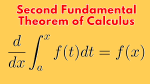
    The Fundamental Theorem of Calculus  establishes a crucial link between differentiation and integration.

     It essentially states that these two operations are inverses of each other, and it provides a way to evaluate definite integrals using anti-derivatives.

    Suppose that f is continuous at a closed interval [a, b] . If the function F is defined on a closed interval [a, b] by:

    $$F(x) = \int_{a}^{x} f(t) dt $$

    where a is a real number, Then F is the anti-derivative of f. in other words, F'(x) = f(x)

    consider the relationships:

    then

    f(x) = x2 and

    Note: We use the dummy variable (t) in the integrand to avoid confusion with the upper limit x.

    Sometimes the fundamental theorem of calculus is interpreted to mean that:

    differentiation and integration are inverse processes to each other.

    It follows that:

    The fundamental theorem of calculus states that:

    if f is continous on an open interval containing a and x and then we first integrate the function f and then differentiate with respect to x, then the result we get is the function f again.

    In other words, the fundamental theorem of calculus argues that differentiation cancels the effect of intergration of continous f(x’).

    in short:

    For example

    Example problem1

    Use the fundamental theorem of calculus to find derivative of the following functions

    (a)

    solution

    NOTE: The best way to benefit from this examples is trying the problem first before looking for answers and attempting again after checking your work against the answer.

    Example problem2

    (b)

    solution to problem 2
    Example problem 3

    Find h'(x) given that :

    solution

    let y=h(x) and u=x2 and hence:

    since u=x2;

    and therefore:

    By use of chain rule:

    which implies u3sinu(2x) = (x2)3sin(x2)2x resulting to:

    =2x7sin(x2)

    Example problem 4

    Consider the expression below, we exchange the limits in the intergral and then change the sign from positive to negative before using the fundamental theorem to solve it.

    Example problems on fundamental theorem of calculus

    We exchange limits and so the sign of the integral so that the upper limit is the valuable x.

    Example problem 6

    Use the fundamental theorem of calculus to solve:

    Solution

    splitting the integral about point zero we have:

    and then exchanging limits in the first integral;

    let u=-x; first part of the expression above becomes;

    from laws of differentiation du/dx=-1 and using chain rule;

    and hence

    and finally

    Revision Exercise

    $$1. \ \frac{d^2}{dx^2}(\int_{x^3}{1789} \frac{1}{t}dt)$$ $$2. \ \frac{d}{dx}(\int_{x}^{x^2}e^{-t^2}dt)dt$$ $$3. \ \frac{d}{dx}(\int_{2}^{3x} sint^2)dt$$ $$4. \ \frac{d}{dx}(\int_{1}^{e^x}ln(1+t^2))dt$$ $$5. \ \frac{d}{dx}(\int_{0}^{sinx}(\sqrt{1+t^2})dt)$$

    Answers to revision exercise

    $$(1.) \ \ \frac{3}{x^2} \ \ (2.) \ \ 2xe^{-4x^4} – e^{-x^2} \ \ (3.) \ \ \ 3sin9x^2$$

    Related topics


  • mastering use of fx-82ms calculators

    The most common calculator used by high school learners is ms fx-82 model. Calculator has many scientific functions that can help a student work out many scientific computations. However, ms fx-82 calculator is non-programmable.

    Casio fx-82MS Scientific Calculator

    The Casio fx-82 MS is a widely used scientific calculator. It is especially favored by students and professionals for its reliability. It also complies with exam requirements.

    Key Features of fx-82 calculator:

    • 240 Functions: Includes trigonometric, statistical, fractional, and exponential calculations.
    • Natural Textbook Display: Shows expressions as they appear in textbooks for easy comprehension.
    • Two-Line Display: Simultaneously displays input and output for clarity.
    • Multi-Replay Function: Allows quick recall and editing of previous formulas.
    • STAT-Data Editor: Supports mean, standard deviation, and regression analysis.
    • 9 Variable Memories: Stores and recalls up to 9 data sets for efficiency.
    • Durable Design: Features robust plastic keys and a protective slide-on hard case.
    • Battery Powered: Operates on a single AAA battery.
    • Non-Programmable: Compliant with exam standards for academic use.
    • Portable and Lightweight: Compact design for easy everyday use.

    Handling Precautions

    • Even if the calculator is operating normally, replace the battery at least after every two years. Continued use after the specified number of years can result to abnormal operation.
    • You should replace the battery immediately after display figures become dim.
    • A dead battery can leak, causing damage to and malfunction of the calculator. Never leave a dead battery in the calculator.
    • The battery that comes with the calculator is for factory testing, and it discharges slightly during shipment and storage. Because of these reasons, its battery life can be shorter than normal. For that reason, consider replacing the battery sooner.
    • Avoid use and storage of the calculator in areas subjected to temperature extremes, and large amounts of humidity and dust.
    • Do not subject the calculator to excessive impact, pressure, or bending.
    • Never try to take the calculator apart.
    • Use a soft, dry cloth to clean the exterior of the calculator
    • Do not use a nickel-based primary battery with this product.
    • use of incompatible batteries such as nickel-based primary battery with fx-82ms calculator can result in shorter battery life and product malfunctioning.

    Turning Power On and Off

    • In order turn on the calculator. Press:

    • to turn off the calculator: press (OFF). that is;

    Adjusting Display Contrast

    To show the display setup screen, press:

    A scree appears as shown:

    press 2 and the use > and < to adjust display contrast. when satisfied with the display settings, press AC button

    use of calculator keys

    To use the alternate function of a key, press [SHIFT] key followed by the key. The alternate function is indicated by the text printed above the key. The alternate function is usually marked with a different color from the main key.

    Basic operations in calculator

    • use AC button to clear all values.
    • To clear memory press shift then mode . Three screens will display as follow:
    • to clear memory press:
    • If your calculator has FIX or SCI on the display press mode three times to get the following screens:

    pressing 3 followed by 2 takes you to a normal mode.

    • If your calculator has RAD or GRAD on the display, then press mode two times to get the following on the screen:

    DEG represents Degree mode and you get there by pressing 1.

    • To display a decimal point as a dot or a comma such as 200.678 or 200, 678, you can press mode button 4 times until DISP 1 is displayed.

    press 1 then forward button once.

    press 1 to separate thousands with a comma(,) or press 2 to separate thousands with dot (.)

    • To initialize the calculator and return the calculation mode and setup to their initial default settings. use the following procedure:

    This operation also clears all data currently in calculator memory.

    Related topics

  • Listening is an art

    Listening is an art

    What’s something most people don’t understand?

    Most people really listen. This is because listen is hard work. We are not always inclined to be good listeners, but we are always distracted by many things when we are listening to somebody speaking. In fact most of people when they are having a conversation with some one, they spend a good part of their brains thinking about what to say in response to what the speaker is saying, consequently, they loose details of the speech in the process. In fact, experts in communication says that an original message is distorted as it passes from one person to another, one reason for this is because of our poor listening habits.

    If we could nurture the habit of effective listening, maybe there would be lesser arguments, quarrels and conflicts. When other people are talking, we should stop this habits of trying to insert and to stamp our stand on what they are saying but strive to understand their point of view. Our desire to safeguard what we know can be found from the way we keep interjecting when someone is speaking but not in seeking clarifications or reciting what they have just said, but to express our opinion and show our experience on the subject in discussion. This way we may loose a valuable wisdom we could have gained from the speaker, because we delighted on talking than listening.

    How should we listen?

    learn more about communication on the communication skills at precisestudy.online

    Related topics