Ohm’s Law and Electrical Resistance are fundamental concepts in electricity explaining the relationship among voltage, current, and resistance. Electrical resistance describes how strongly a material opposes the flow of electric current. Understanding these concepts is essential for analyzing circuits, designing electrical systems, and explaining how electronic devices operate in everyday life.
One of the most important principles that helps us understand how electricity behaves in a circuit is Ohm’s Law. This law explains the relationship between voltage, current, and resistance in an electrical conductor.
Electricity powers almost every device we use today, from mobile phones and televisions to electric cars and industrial machines.
In this lesson, we shall explore Ohm’s Law and the electrical resistance, how it is verified experimentally, the meaning of electrical resistance, and the factors that affect resistance in conductors.
What is Ohm’s Law?
Ohm’s Law states that:
The current flowing through a conductor is directly proportional to the potential difference across it, provided temperature and other physical conditions remain constant.
This means that when the voltage across a conductor increases, the current flowing through it also increases proportionally.
The mathematical expression of Ohm’s Law is:
V=IR
some of the physical conditions includes pressure and tensional forces on the conductor.
Where:
- V = Voltage (Volts)
- I = Current (Amperes)
- R = Resistance (Ohms)
Investigating the Relationship Between Current and Voltage in ohm’s law
To verify Ohm’s Law, a simple experiment can be carried out using a nichrome wire.
Apparatus Required
- Two-metre nichrome wire
- Two dry cells
- Ammeter
- Voltmeter
- Rheostat
- Switch
- Connecting wires
Experimental Setup to study ohm’s law and electrical resistance
- Using a nichrome wire, make a coil of as many turns as possible
- Set up the circuit as shown in figure below

- Set the current flowing in the circuit to the least possible value
- with help of the rheostat, vary in steps the current flowing in the circuit and not e the corresponding voltage drop across the coil.
- Record the results in the table below
| Current (A) | ||||
|---|---|---|---|---|
| Voltage (V) |
Observation of ohm’s and electrical resistance
As the current flowing through the nichrome wire increases, the voltage across the wire also increases. When voltage is plotted against current, the graph obtained is a straight line passing through the origin.

The table below represents a sample data from such an experiment.
| Current (A) | 0.1 | 0.2 | 0.3 | 0.4 |
|---|---|---|---|---|
| Voltage (V) | 1.2 | 2.4 | 3.6 | 4.8 |
when this data is plotted on a grid, a graph as shown is obtained.

Points to note:
The circuit is connected such that:
- The ammeter measures the current flowing through the wire.
- The voltmeter measures the voltage across the nichrome wire.
- The rheostat is used to vary the current in the circuit.
Data Analysis and conclusions
The gradient of the graph will be given by:
from the graph, the following observations can be obtained:
As the current increases, the voltage across the coil also increases.
The graph obtained when voltage is plotted against current is a straight line passing through the origin.
Therefore:
- voltage is directly proportional to current
- gradient of the graph is a constant. This constant gives the resistance of the conductor used.

This straight-line graph confirms that voltage is directly proportional to current.
Understanding Resistance
From the experiment, the ratio of voltage to current remains constant. We can verify the ohm’s law with the same procedure described above when we replace a coil with a standard resistor. The graph of current against voltage is a straight line through the origin.

From the graph above:
From V ∝ I:
V=constant(K)x I
The constant which we represent with K is the resistance of the conductor.
hence;
V=IR where V is the potential difference across the conductor.
Resistance can therefore be calculated using:
The SI unit of resistance is the ohm (Ω).
An ohm is defined as the resistance of a conductor when a current of 1A flowing through it produces a voltage drop of 1 V across it’s ends.
A conductor is said to have a resistance of 1 ohm if a current of 1 ampere flows through it when a potential difference of 1 volt is applied across it.
an ohm have some other units like:
1 kilo ohm(KΩ) = 1000Ω
1 mega ohm(MΩ) = 1 000 000Ω
Worked Examples
Example 1
A current of 2 mA flows through a conductor of resistance 2 kΩ. Calculate the voltage across the conductor.
solution:
Using Ohm’s Law:
V=IR
Example 2
Calculate the current flowing through a 50 Ω resistor connected to a 10 V battery.
solution
from ohm’s law:
Example 3
A starter motor requires a current of 50 A from a 12 V battery. Determine the resistance of the motor.
solution
Ohmic and Non-Ohmic Conductors
Ohmic Conductors
Conductors that obey Ohm’s Law are called Ohmic conductors.
Examples include:
- Nichrome wire
- Metallic resistors
For these conductors, the graph of voltage against current is a straight line.
Non-Ohmic Conductors
Some conductors do not obey Ohm’s Law. These are known as Non-Ohmic conductors.
Examples include:
- Filament lamps
- Thermistors
- Semiconductor diodes
- Electrolytes
Their voltage-current graphs are curved instead of straight.


Electrical Resistance
Electrical resistance is the opposition offered by a conductor to the flow of electric current.
Resistance occurs because electrons moving through a conductor collide with atoms and impurities inside the material. These collisions reduce the flow of charge and produce heat energy.
Electrical Resistance Animation
This animated illustration demonstrates how electrical resistance occurs inside a conductor. Electrons flowing through the wire collide with vibrating atoms, causing opposition to current flow.
How Electrical Resistance Works
In a metallic conductor, electric current is carried by moving electrons. As these electrons move through the wire, they collide with atoms and impurities present in the conductor.
These collisions oppose the movement of electrons and reduce the flow of electric current. This opposition is called electrical resistance.
When temperature increases, atoms vibrate more strongly, causing more collisions and therefore increasing resistance.
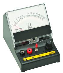
An instrument used to measure resistance is called an ohmmeter.


5
Factors Affecting Resistance
Several factors determine the resistance of a conductor.
1. Length of the Conductor
The resistance of a conductor increases with its length.
that is: R ∝ l
hence; resistance = constant x length
i.e = R = Kl ————————(i)
for a given conductor:
As the length of the conductor increases, the resistance increases because of the increased number of atoms that are available to hinder the flow of electrons.
A longer wire contains more atoms that obstruct the movement of electrons, leading to greater resistance.
2. Cross-Sectional Area
Resistance decreases when the cross-sectional area increases A.
That is: resistance is inversely proportional to cross section area(A) of the conductor.
A conductor with a larger cross-section area(A) has many free electrons for conduction, hence better conductivity.
Thicker wires allow more electrons to flow easily and therefore have lower resistance.

Combining (i) and (ii) for a conductor with uniform cross-section area;
The constant value in the equation above is referred to as the resistivity(ρ)of a material. It is practically the resistance of sample of a material of unit length and unit cross-section area at a given temperature. The unit of measurement for resistivity(ρ) known as ohmmeter(Ωm).
The table below shows resistivity of some common materials
| Material | Resistivity (Ωm) | Common Uses |
|---|---|---|
| Silver | 1.6 × 10⁻⁸ | Contacts on some switches |
| Copper | 1.7 × 10⁻⁸ | Connecting wires |
| Aluminium | 2.8 × 10⁻⁸ | Power cables |
| Tungsten | 5.5 × 10⁻⁸ | Lamp filaments |
| Constantan | 49 × 10⁻⁸ | Resistance boxes, variable resistors |
| Nichrome | 100 × 10⁻⁸ | Heating elements |
| Carbon | 3,000 × 10⁻⁸ | Radio resistors |
| Glass | 10¹⁰ – 10¹⁴ | Electrical insulators |
| Polystyrene | 10¹⁵ | Electrical insulators |
Example problem in resistance
Two wires of A and B are such that the radius of A is twice that of B and the length of B is twice that of A. if the two are of the same material, determine the ratio:
solution:
Therefore, after rearranging the expression:
since lB = 2lA ; 2RB = RA


3. Temperature
For metallic conductors, resistance increases with temperature.
Heating causes atoms in the conductor to vibrate more vigorously. This increases collisions between electrons and atoms, making it more difficult for current to flow.
Resistivity of Materials
Resistivity is a property that shows how strongly a material opposes electric current.
Materials such as:
- Silver and copper have low resistivity and are good conductors.
- Glass and polystyrene have high resistivity and act as insulators.
Temperature also affects resistance:
- In metals, resistance increases with temperature.
- In semiconductors, resistance decreases with temperature.
Resistors
A resistor is an electrical component designed to provide resistance in a circuit.
Resistors are used to:
- Control electric current
- Reduce voltage
- Protect circuit components
- Produce heat in appliances
Most wire-wound resistors are made using materials such as:
- Manganin
- Constantan
These materials are preferred because their resistance changes very little with temperature.
Fixed Resistors
Fixed resistors have a constant resistance value.
Types of Fixed Resistors
1. Wire-Wound Resistor
This resistor is made by winding resistance wire around an insulating core.
Features:
- High durability
- Can handle large currents
- Common in power circuits
2. Carbon Resistor
Made using carbon material.
Features:
- Cheap and widely used
- Small in size
- Used in electronic circuits
Resistor Symbol
The electrical symbol of a resistor is represented by a zigzag or rectangular shape depending on the standard used.
Variation of Resistance with Temperature
Different materials respond differently to temperature changes.
Metals
Resistance increases as temperature rises.
Thermistors
Resistance decreases as temperature rises.
Constantan
Resistance remains nearly constant despite temperature changes.
This behavior is important in designing temperature-sensitive circuits.
Variable Resistors
A variable resistor allows resistance to be adjusted manually.
The resistance changes when a sliding contact moves along the resistance track.
Applications include:
- Volume controls in radios
- Light dimmers
- Fan speed regulators
Rheostat
A rheostat is a variable resistor with two terminals.
It is used to control current in a circuit.
As the slider moves:
- The effective length of the resistance wire changes
- Resistance changes accordingly
Increasing the resistance reduces current flow.
Potentiometer
A potentiometer is a variable resistor with three terminals.
It is used to:
- Divide voltage
- Control signal levels
- Adjust volume in audio systems
How It Works
A sliding contact moves along the resistor track, selecting different voltage levels.
Potentiometers are commonly used in:
- Audio amplifiers
- Electronic control systems
Non-Linear Resistors
These resistors do not obey Ohm’s Law strictly because their resistance changes non-linearly with voltage, temperature, or light.
Examples include:
- Thermistors
- Light-dependent resistors (LDRs)
Thermistor
A thermistor is a temperature-dependent resistor.
Characteristics
- Resistance decreases as temperature increases.
- Used in heat-sensitive circuits.
Applications
- Temperature sensors
- Fire alarms
- Electronic thermometers
Light-Dependent Resistor (LDR)
An LDR changes resistance according to the amount of light falling on it.
Characteristics
- High resistance in darkness
- Low resistance in bright light
Applications
- Automatic street lights
- Camera light sensors
- Burglar alarms
Importance of Resistors in Daily Life
Resistors are found in almost every electrical and electronic device.
They help to:
- Protect circuits from excessive current
- Control electrical energy
- Improve device performance
- Enable automatic sensing systems
Without resistors, modern electronics would not function safely or efficiently.
Resistors play a vital role in electrical and electronic circuits. From fixed resistors to thermistors and LDRs, these components help control current, voltage, temperature, and light sensitivity in devices we use every day.
Understanding how resistors work gives students a strong foundation in physics and electronics, preparing them for more advanced studies and practical applications in technology.
Conclusion
Ohm’s Law is one of the most fundamental principles in electricity and electronics. It helps us understand how voltage, current, and resistance are related in electrical circuits. Through experiments and graphical analysis, students can clearly observe the direct relationship between voltage and current in Ohmic conductors.
Understanding electrical resistance and the factors affecting it is essential in designing safe and efficient electrical systems used in homes, schools, laboratories, and industries.
Whether you are studying basic physics or advanced electronics, mastering Ohm’s Law provides the foundation for understanding the behavior of electric circuits.
Related Topics
- Current and potential difference
- Resistor
- Introduction to electronics
- Intrinsic and extrinsic semiconductors
- Simple electric circuits

Leave a Reply