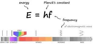
The quantum theory of light proposes that light travels in bundles of energy, known as a photon. In 1909, Max Plank proposed that light energy is propagated as a small packets of energy that are discrete. Each packet of energy is referred to as a quantum of energy. The discrete amount of energy are called photons and posses a definite energy that can be determined from the frequency of the light waves.
Energy E of a photon can be determined from the relation E=hf. Here, h is a constant value known as Plank’s constant. Max Plank introduced it in his theory.
Plank’s constant h is given as h=6.63 X 10⁻³⁴Js
From the general equation of a wave:
c=fλ
where λ is the distance between two particles in a wave usually referred to as the wavelength.
expressing f in terms of speed of light:
f=cλ
substituting for f in the equation E=hf;
$$E=h\frac{c}{f}$$
c is the speed of an electromagnetic radiation in vacuum and is given as 3.0 x 10⁸ms-1
c and h are constants in the equation and so energy of a wave is only determined by the wavelength. From the equation, energy increases when wavelength reduces.
Energy of a photon is therefore inversely proportional to the wavelength.
Example problem on the Quantum theory
compare energy contained in a photon of red light of wavelength 6.7 x 10⁻⁷ m and violet light of wavelength 3.4 x 10⁻⁷m. (take Plank’s constant as 6.63 X 10⁻³⁴Js)
solution
The energy carried by the red light will be given as :
Therefore energy carried by red light photon will be:
E = 5.85 X 10⁻¹⁹ Joules
As can be determined from the above working, violet light has more energy compared to red light as it has shorter wavelength.
Light energy in a Photons
Most of waves are considered continuous and progress as in figure below:
A continuous wave can carry any amount of energy depending on the amplitude and frequency. There is no minimum energy of the wave but energy may be reduced simply by decreasing amplitude of the wave.
Quantum theory however shows that electromagnetic waves travels as wave packets also known as photons that are imagined to travel as shown.
Each photon carries a definite amount of energy that is proportional to the frequency of the radiation.
Example problem
Determine an energy carried in a photon of an x-ray with a frequency of 8.0 x 10¹⁷ Hz.
solution
Energy E = hf
E=6.63×10−34Js×8.0×1017 Hz
=5.304 X 10⁻¹⁶ J
Threshold Frequency
Radiations below certain frequencies does not eject electrons from a metal surface no matter how intense the light will be.
The minimum frequency needed for a wave so that it is able to eject an electron from a metal surface is known as the threshold frequency fo.
If the frequency is below a certain value, it will be absorbed by the metal surface onto which it falls but no electron will be ejected to the surface.
Threshold wavelength
if the threshold frequency is fo ,the speed of the wave can be determined by:
c= foλo where λo is known as the threshold wavelength that corresponds with the threshold frequency. It is the maximum wavelength beyond which an electron wont be ejected from a metal surface.
in other words:
$$\lambda_o = \frac{c}{f_o}$$
The quantum theory: Work Function
The work function wo is the minimum amount of energy needed to eject an electron from a metal surface. It represents work that need to be done in order to remove a negatively charged electron from a metal atom by overcoming the force of attraction of the positively charged nuclei of the atom.
Different atoms have different magnitude of attractive forces between its nucleus and the electrons. This means different energy will be required to eject electrons from different metal surfaces. Therefore, the value of work function differs from one metal to another.
Some applications of C.R.O includes measuring of electrical potential as a voltmeter, television displays and in measuring frequency of signals.
applications of C.R.O as a voltmeter
C.R.O can be used as a voltmeter when it time base circuit is switched off and the voltage to be measured is connected across the Y-plates while the X-plates are earthed.
The vertical displacement of the bright spot on the screen is measured and the sensitivity of the C.R.O is adjusted to determine number of volts per units of displacement along the vertical scale.
The number of volts per unit of division is the sensitivity. The voltage can the be determined as:
Voltage = displacement x sensitivity
Sensitivity is adjusted using the Y-gain knob which automatically connects the input signal through an application system.
Amplification system ensures that even very signals are raised to the levels where they cause measurable deflection of the beam.
application of C.R.O as a voltmeter is considered a superior voltmeter compared to convectional ones because of the following reasons:
can measure large voltages without being damaged
can measure both direct and alternating voltages
Has infinite resistance hence takes no current meaning that it rarely interferes with the circuit into which it is being connected.
It responds instantaneously unlike ordinary meters whose meters swings momentarily about the correct reading due to inertial.
Example Problem on usage of C.R.O as a voltmeter
A D.C voltage of 80V when applied to the Y-plates of a C.R.O causes a deflection of the spot as shown in figure below:
(i) Determine sensitivity of the y-gain
(ii) show what will be formed on the screen if an a.c of peak voltage 64V
is fed onto the Plates.
solutions
(i)
spot deflection on the screen from the center of the screen = 5 divisions
Voltage in a.c with be a straight line 4 divisions above the central line and 4 divisions below it as shown below
Example applications of C.R.O
The Y-gain of a CRO has a sensitivity of 500V/div. An a.c voltage of 2500V is connected across the Y-plates. show what is observed on the screen.
solution
Voltage = sensitivity x number of divisions
We need to determine the number of divisions that a signal will be displaced vertically.
$$\text{Number of divisions} = \frac{voltage}{sensitivity} = \frac{2500 V}{500 V / div} = 5 divisions $$
Numberofdivisions=Voltagesensitivity
=2500V500v/div=5divisions
Hence a straight vertical line will be formed on the screen covering 5 divisions above the x-axis and 5 divisions below it as shown
applications of C.R.O to measure frequency of an a.c signal
The signal is fed into the Y_plates of a C.R.O with the time base on. The time base control is then adjusted to give one or more cycles of the input signal on the screen. By adjusting the time base control, we can determine the number of cycles made on the screen from the periodic time T. Frequency can then be calculated from f=1/T.
Example question on applications of C. R.O
Figure below shows a trace on the screen for an signal connected to the Y_plates of a CRO with time base on.
Given that the time base control is 20ms/div and the Y-gain is at 80V/div, determine:
(i) frequency of the a.c signal
(ii) The peak voltage of the input signal
solution (i)
Time base settings is 20ms/div
Number of waves shown on the screen =3.25
7 div is covered by 2.5 waves.
1 wave = 7.0/2.5 = 2.8 divisions
Time taken to complete 1 wave (periodic time) = 2.8 div x 20ms/div = 56ms = 56 x 10-3s
Frequency=1T
And so the frequency will be given by:
Frequency=156∗10−3s
0.01786 x 10³ Hz =17.86 Hz
solution (ii)
Y-gain =80div
Approximate deflection as about 2.2 divisions as per the graph
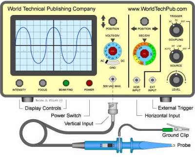
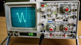
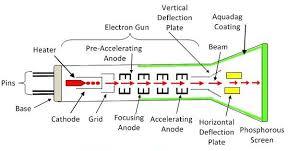
The cathode ray oscilloscope(CRO) is an electrical test device used to produce waveforms in response to several input signals. It was originally known as an oscillograph. The cathode ray oscilloscope is a development of the cathode ray tube. A standard cathode ray tube has the following parts:
The electron gun
A system of plates for deflecting the electron beam
An evacuated strong glass envelope
A fluorescent screen at one end of the glass envelope
Inside the cathode ray oscilloscope, the main parts are as shown.
we now discuss each of the components making the CRO.
cathode ray oscilloscope(CRO): The electron gun
It is the component that supplies the electrons. After producing electrons, it accelerates them towards the screen and focus the beam to a point on the screen. The electron gun consists of :
a heated cathode
a grid to control electrons flow
anodes to accelerate and focus the electron beam
Each of the above parts is maintained with a direct current potential from E.H.T source and a potential divider as shown.
Electron gun in 2-DElectron gun in 3DA practical electron gun
Cathode is coated with thorium or strontium oxides .These which are preferred because they need little energy to extract electrons from them.
Anodes are made of cylinders and discs maintained at high positive potential relative to the cathode . This makes them able to attract the emitted electrons and direct them towards the screen.
Cathode ray oscilloscopes Anodes as focusing beam
Focusing the cathode beam involves using two anodes that are at different potentials.
consider the diagram below:
Anode A1 is at higher potential compared to anode A2. There is an electric field between the two anodes and there direction is such that to converge a diverging beam that is leaving the cathode through aperture of anode A1.
Electric field intensity increases when the potential difference between the two anodes A1 and A2. Increasing Electric field intensity increases the degree of focusing.
The potential difference is controlled by the potential divider P which is the focusing knob on the control panel.
The CRO grid
In cathode ray oscilloscope, grid is a small hollow cylinder with a small hole at the end. Grid is used to control the intensity of the beam. The figure below shows cathode ray illustrated in a cathode ray tube.
The potential divider is used to make the grid more negative or less negative. Sliding it to the left increases it’s negative potential and sliding it to the right reduces the negative potential. When the grid is made less negative, more electrons are allowed to pass through it and when it is more negatives, fewer electrons are allowed to pass through.
Because Intensity of the spot on the screen is determined by the by the number of electrons striking the screen, grid is therefore used to control the intensity of the beam and hence brightness of the spot on the screen. The brightness knob controls the potential divider that varies the potential difference between the grid and the cathode. see the diagram below:
The cathode ray oscilloscope deflection System
Deflection system is used to alter direction of the beam horizontally or vertically. If the deflection system is off or absent, the the beam will strike the screen at the center. The vertical deflection system causes the beam displaced up or down from the center of the screen. Horizontal deflection system displaces the beam on either sides of the center spot.
the cathode ray oscilloscope Vertical Deflection System
They causes the beam to deflect vertically across the screen when they are switched on. Vertical deflection system is also known as the Y-plates and their signal is usually fed in through the Y-Input terminal.
Consider the setup below:
When the switch is closed, Y1 is at positive potential while Y2 is at negative potential. The beam is therefore attracted towards plate Y1 and so the beam hits the screen at B.
If polarity is changed such that Y2 is the positive, bright spot is observed at point C on the screen. This shows that the beam has bent towards Y2 . If There is a constant reversal of the polarities of the vertical deflection system, the spot on the screen keeps shifting from B to C to B at the frequency of the reversals.
Most often, an a.c is connected to the vertical deflection system and so the spot is observed moving up and down according to frequency of the a.c voltage.
When the frequency of the a.c voltage is high, the persistence of vision makes the movement of the spot appear as a vertical straight line. The movement goes up and down on the screen. see the figure below:
cathode ray oscilloscope horizontal deflection system
They are also referred to as the X-plates as they cause the deflection of the spot to occur parallel to the X-axis.
consider the set up below:
When the plates are arranged as above, x1 is at positive potential. As a result, the electron beam is deflected horizontally towards M. When The polarity are changed such that x2 is now the positive one, the beam is deflected towards N.
A varying voltage is applied to the X-plates from a special circuit known as the time base. The time base circuit moves the bright spot at a constant speed. It travels from one end of the screen to the other. When it reaches the end, it disappears momentarily before it reappears again and moves across.
The moment the spot is moving across the screen is known as the sweep. The moment it is disappearing from the screen is known as the flyback
Consider the figure below.
Explaining the time base wave
When the time base circuit is switched on, the voltage increases uniformly to peak (sweep) and then drops suddenly(flyback).
Increase of voltage causes the bright spot to move horizontally at a uniform speed until a peak voltage is reached. The time base voltage then drops suddenly to a maximum negative value. This causes the spot to fly back to the starting point at the other end of the screen. The voltage builds up again and the process is repeated in cycles.
The movement of the spot across the screen (sweep) can be controlled using the time base control knob. This knob operates the frequency of the time base voltage. Increase of frequency results to reduction of sweep time. When the frequency is low, the spot moves slowly across the screen. You can follow it with your eye as shown in the diagram below.
When frequency of the time base is high, the movement of spot traces a permanent horizontal line across the screen as shown below.
If input voltage at the y-plates and the time base voltages are switched on simultaneously. The spot is deflected vertically and horizontally at the same time causing a two dimensional movement in form of a sine curve on the screen. The figure below illustrates the Y-plates and time base circuit.
In the figure, we are shown the signal that would be formed when the two circuits are working simultaneously.
The cathode ray oscilloscope (CRO) screen
It is usually coated with a fluorescent substance called phosphor. Phosphor, which is made from zinc sulphide glows when electrons collides with it. This glow persists for about 0.05 seconds and so the screen continues to glow even after the beam has passed the point of impact.
The persistence of the phosphor allows the waveform to be seen. Persistence of vision in the eye also enables this observation on the screen. Inside of the tube is coated with graphite because of the following functions:
conduction of the electrons to the earth
shielding the beam from external electric fields
Accelerating electrons towards the screen since it has the same potential as the anodes.
The following video shows how to use the cathode ray oscilloscope:
The term “properties of cathode rays” refers to the various physical characteristics and behaviors observed when cathode rays are studied under different conditions.
properties of cathode rays includes:
They travel in a straight line
causes fluoresce or glow to certain materials
they are charged
possesses kinetic energy
pass through thin materials demonstrating their ability to penetrate objects to varying degrees. This depends on the material’s density and the energy of the rays.
ionize gases
The charge-to-mass ratio of cathode rays (electrons) is relatively high. A property used to identify the electron and distinguish it from other particles.
Deflection by Magnetic Fields
Showing that cathode rays travels in a straight line
When an opaque object is placed between the screen and the cathode in the path of the cathode rays, a sharp shadow is cast on the screen.
Cathode rays causes certain substances to glow or fluoresce
Fluoresce materials are materials that glows when electromagnetic energies falls on them. such materials includes zinc sulphide, Fluorescein, Rhodamine, Coumarin, Acridine Orange and Quantum Dots.
when cathode rays falls on screen coated with the fluoresce materials, the fluoresce material glows.
showing that cathode rays are charged
Cathode rays are deflected by both magnetic and electric fields.
Inside the magnetic field, the cathode rays are deflected towards the positive plate showing that they are negatively charged. Remember that opposite charges attract while while same charges repel from the basic law of charges. see the figure below:
When cathode rays passes through magnetic field, they are deflected in the direction determined by Fleming’s left-hand rule. The deflection in magnetic field shows that they are negatively charged as shown in figure below.
Cathode rays have kinetic energy
The deflection of cathode rays in a magnetic field shows they are moving, and therefore possess kinetic energy. By measuring how much the cathode rays bend in the magnetic field, you can calculate their velocity. Using the velocity, you can compute the kinetic energy of the cathode rays.
When cathode rays are suddenly stopped by a metal target, they can produce x-rays. This confirms that they are actually a stream of fast moving electrons.
Exam Questions on properties of cathode rays
Figure 14 shows a cathode ray tube. A metal plate is placed between the anode and the screen.
(I) State with reason what would be observed on the screen when the cathode rays are produced. (2 marks)
(ii) State the effects on the cathode rays produced when the anode is increased. ( 2 marks)
Exam questions on Cathode rays are an important topic in physics and chemistry. They test knowledge on key curriculum areas that includes:
Atomic Structure
Electricity and Magnetism
Properties of Matter
Electron beams
Charge-to-mass ratio (e/m)
Millikan’s oil drop experiment
etc.
below are questions commonly tested in physics examinations on this topic;
1. The figure 1 below represents a cathode ray oscilloscope (C.R.O) (i) Name the parts labeled A and B (2 marks)
Figure 1
A.…….………………………………………………………………………………………… B.…….…………………………………………………………………………………………. ii) What are the functions of parts labeled C and D (2 marks) C ………………………………………………………………………………………………… D …………………………………………………………………………………………………. iii) Explain how electrons are produced. (1 mark) …………………………………………………………………………………………………… ……………………………………………………………………………………………………. iv) Give a reason why the tube is evacuated. (1 mark)
2. State the function of the grid in a cathode ray tube (CRT) (1 mark)
3. State two reasons why the CRO is a more accurate voltmeter than a moving coil voltmeter. (1 mark)
4. Figure 2 shows a cathode ray entering into a region between two charged plates.
Complete the diagram to show the path of the ray in the electric field. (1 Mark)
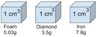
Exam questions on density often involve several concepts. This includes; calculating density, comparing densities of different substances, or understanding how density relates to buoyancy and floating. Density is a measure of how much mass is packed into a given volume. It’s calculated by dividing an object’s mass by its volume.
Exam Questions on density
1.(a) The level of water in a measuring cylinder rises from the 50 cm3 mark to 55.7 cm3 marks when a metal block weighing 45 g is submerged in the water in the cylinder.
(i) Calculate the density of the metal block
(ii) State two differences between density and relative density.
2. (b) In an experiment to determine the density of solid S which is not soluble in water. A student obtained the following;
-Mass of empty density bottle= 20 g
-The Mass of density bottle when full of water =45 g
-Mass of density bottle with small quantity of solid S =152 g
-Mass of density bottle with small amount of solids S topped up with water =167 g.
Given that the density of water is 1 g/cm3.Find; i. The volume of the density bottle
ii. The mass of the solid S iii. The volume of the solid S
2. The volume of a solution was measured as below. If the mass of solution is measured to be 60.75 grams, what is the density of the solution? (2 marks)
solution level as seen on a measuring cylinder
3. What is the mass of a cylinder of lead that is 2.50 cm in diameter, and 5.50 cm long. The density of lead is 11.4 g/cm3.
(i) Calculate the volume in two decimal places of the cylinder. Take π=3.14 (3 marks)
(ii) Determine the mass of the cylinder. Leave your answer as a whole number. (3 marks)
4. Exam questions on density
4. The mass of an empty density bottle is 20 g. Its mass when filled with water is 40.0 g and 50.0 g when filled with liquid A.
(i) Determine the mass of water in kilograms. (3 marks)
(ii)Find the mass of liquid A (in kilograms). (3 marks)
(iii) Find the volume of water. (2 marks)
Calculate the density of liquid A if the density of water is 1,000 kgm-3. (2 marks)
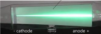
Cathode rays are streams of negatively charged particles, or electrons, which are accelerated from a cathode to the anode within a vacuum tube by an electrical potential.
These rays travel to the positively charged anode, creating a visible beam. They are also known as electron beams and were instrumental in the discovery of the electron.
Before the electrons are accelerated, they must be extracted from a atoms and be on the surface. Electrons are first extracted from from the nuclei to a metal surface when the metal is heated. The heat energy raises the energy of an electron. This enables it to break loose from the force of attraction of the nuclei. This process where electrons are emitted to the surface is known as thermionic emission.
When a material is heated, its atoms vibrate more vigorously. This thermal energy can be transferred to the electrons in the material. If the temperature is high enough, some electrons gain enough energy to overcome the work function of the material. Work function is the minimum energy needed for an electron to escape from the surface of the material. It escapes into the vacuum or surrounding environment.
Thermionic Emission for cathode rays
In thermionic emission, a cathode is heated from low voltage supply so that electrons can be extracted to the surface. Another higher voltage is then used to accelerates the electrons produced towards an anode. A typical setup used for thermionic is as shown below.
A cathode which is inside the evacuated glass tube is made with mixture of barium oxides and strontium oxide. The resulting metal oxide has a low work function. This means that the minimum energy required to remove an electron from its atom to the surface is low.
In the setup a low voltage of about 6V drives a current through the heating filament which then heats the cathode
Initially the reading on the milliammeter(mA) is zero. When the heater circuit is switched on, some current is observed on the milliammeter after some time. This means that the current circuit between the cathode and the anode has been completed. There is a wide gap between the anode and the cathode. However, when the heater current is switched on, the heater circuit is complete in the gap.
This is because cathode the electrons produced by the cathode are able to move to the anode across the gap. How do they do that?
The hot cathode emits electrons which are then attracted to to the anode due to the 12V accelerating potential. This acceleration ensures electrons are able to move across the gap hence making the circuit complete. This setup allows us to observe thermionic emission. It helps explain the cathode rays inside the evacuated glass tube we call a cathode ray tube.
Production of cathode rays
Cathode rays are usually produced in cathode ray tube (CRT).
A cathode ray tube
Electrons produced at the cathode by thermionic emission are accelerated towards a fluorescent screen. This fluorescent screen connected to the anode which is connected to the positive terminal of an extra high tension (E.H.T) source. When cathode rays are stopped by the fluorescent screen, the kinetic energy of the cathode causes the screen to glow.
The reason the tube is evacuated is to ensure electrons do not collide with gaseous particles before reaching the screen. If electrons collides with other particles, ionization of the gas in the tube occurs. This is found to be causing different observations from the one intended. Collision with some other particles can cause electrons to loose their energy and probably not able to reach the screen. The movement of cathode rays in a cathode ray tube is illustrated in the table figure below:
Questions
What is thermionic emission
Illustrate production of cathode rays using a suitable diagram.
Explain why it is important for a cathode ray tube to be evacuated.
Domestic wiring refers to the electrical wiring within a residential building. It encompasses the components and circuits that provide power for lighting, appliances, and other electrical needs. In domestic wiring, we studies: installation and connection of wires, switches, outlets, and other electrical devices. Understanding domestic wiring, ensures safe and reliable power supply.
what is domestic wiring
Domestic wiring refers to electrical connections that allows use of electric powers supplied by power providers .
Electrical power is usually supplied at 240V after the high voltage transmitted is scaled down through a local transformer. The high voltage transmission from power source could be 11000 V or more. The consumer will need only 240 V, therefore a step-down transformer will be needed.
Electric power is connected to a homestead from the transformer by use of two-wire cable. One cable is earthed at the transformer. The earthed wire is referred to as the neutral wire .
The earthed considered to be at zero electrical potential while the other wire is referred to as the live wire. The cable goes through the electrical company fuse box . The live wire is connected to a 60 A or high fuse value. The cable is then connected to the power meter where energy consumption is registered. From there it passes on to the consumer’s fuse box as illustrated.
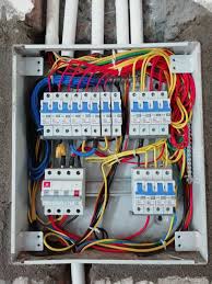
consumers fuse box in domestic wiring
It is the central part of an electrical system. It distributes electrical power and provides circuit protection. The figure below illustrates a common fuse box connections in a domestic wiring.
Consumers fuse box
Here’s an overview of what it includes and what you should know:
The main switch
This is a double -pole switch which disconnects both the live and the neutral wire at the same time. disabling all the circuits in the house when needed. It is the main connecting link between external supply and household wiring . however, but we can have more than one mains switch.
The live busbar
This is a brass bar to which all live wires and the fuse are connected to. It connects to the live wire through the main switch. It connects the live wire of each circuit through a fuse.
Neutral busbar
This is the brass bar to which all neutral wires are connected to in domestic wiring.
Earth terminal
It is the earthed cable in the fuse box connected to the thick copper bar buried deep in the earth. It can also be earthed through water piping.
fuses
They are made of short thin wire mostly an alloy of cooper and tin. The alloy wire should have a low melting point. Fuses are used to safeguard against excess current in the circuit. When current exceeds the fuse rating, the wire gets very hot and melts hence disconnecting the circuit.
The melting disconnects the excess current which would have otherwise damaged the electrical appliances. Fuses also reduces risk of fire incase there is overheating in a circuit.
An electric fuse
fuse symbol (old)
fuse standard symbols
The circuit breaker
Circuit breakers are preferred over fuses protect electrical components from excessive flow for current.
When excess current flows through the circuit, increased magnetic power of the electromagnet opens the switch. This stops electric current flow. Once the problem causing the excessive current flow has been corrected , the switch is closed by mechanical means.
An advantage of circuit breakers over the fuses is that the circuit is broken simultaneously where the fuse melts slowly. The circuit breaker reset itself once the electric surge is corrected. This is unlike fuse that need to be replaced when it’s fuse wire melts.
common symptoms of electrical problems in domestic wiring
repeatedly Tripping circuits
Burning smell or scorch marks
Buzzing sounds
Distribution of power from the consumers unit
House wiring systems distribute electricity throughout a building. Common systems include cleat, casing & capping, batten, lead sheathed, and conduit wiring. conduit is considered the most popular and safest, involving pipes (metal or PVC) to house wires.
consider the setup below:
Each component is has a wire running from the live busbar through an appropriate fuse or circuit breaker. There is also a return wire running from the neutral busbar to the output terminal.
Except for the lighting circuit, other circuits have an earth connections running from the earth terminal to the socket. Appliances that requires earthing are automatically earthed through the socket making them safe to handle. Not earthing some appliances exposes danger to the consumer because they can be shocked while using them.
The lighting circuit
In lighting circuit, lamps are connected in parallel so that they operate at the same mains voltage and also operate independently. Switches are placed on live wire for safety purposes.
If the switch was on neutral wire, the wire would still be connected to the mains potential even when the switch is off. This would cause an electric shock when one handles any conductor linked to the live wire.
since lighting circuit carries relatively low current, the wire used is relatively thinner than those of other circuits. In an ordinary house, power for the lighting is usually supplied through 5A fuse .This is because each lamp takes only a small current.
The two ways switch circuit
A two-way switch circuit allows a lamp or other electrical device to be controlled from two different locations. This is achieved by using two or more switches that are connected in a specific way.
In this circuit, an electric lamp can be operated by any one of the two switches. The circuit allows a bulb to be put on by one switch and be put off by the other switch. The most common application is for controlling staircase lights from both the top and bottom of the stairs. A switch at the bottom of the staircase can be used to put on the light. The switch on the top of the staircase then turns it off. A lamp can be turned on by a switch at the door. Another switch at the other end of the room turns it off.
Figure below illustrates a two way switch:
when the contact is made at poles A and B as illustrated on the diagram, the bulb lights. The same thing happens when contact is made at C and D simultaneously.
To put off the bulbs at point P, the switch is made to make contact at C while Q is in contact with B. To put on the bulb again at Q, the switch is made to contact D. At that point, P and C are in contact with each other.
The ring mains circuit
A ring main circuit, also known as a ring circuit. is a type of electrical circuit used in many UK homes to distribute electricity to power sockets. It’s characterized by a looped cable that runs from the consumer unit (fuse box), through multiple sockets, and back to the consumer unit. This looped design allows electricity to reach a socket from either direction, reducing the load on the cable compared to a single-direction radial circuit
The figure below illustrates the ring mains circuit.
The power for the sockets in the various rooms is tapped at convenient points from the loop. The lop arrangement of the cable enables a double path for the current. The loop arrangement also effectively increases the thickness of the wire used. This reduces the risk of overloading the circuit when several sockets are in use.
Appliances using the ring main circuit are provided with a third wire connected to the casing. From the power socket, the third wire links with the earth terminal at the consumer unit through the mains circuit earth wire. If the live wire accidentally touches the casing, it makes it live. A large current flow through the earth wire. The large current will causes the fuse to blow, cutting off the current. Anyone handling the appliance will thus be safe from possible shock.
The cooker circuit
A cooker circuit refers to the electrical circuit dedicated to powering an electric cooker. Typically a hob and oven, in a domestic setting. It’s designed to handle the high power demands of cooking appliances. It usually involves a dedicated circuit breaker, a cooker control unit (CCU) and specific wiring configurations.
The cooker circuit has the same connection and design with water heater circuit. They are both supplied with own electric circuits. These are earthed and their wires are relatively thicker than those for the lighting circuits as they carries large currents.
The three pin plug
A three-pin plug is a type of electrical plug used to connect an appliance to the power supply. It has three metal pins (or prongs) that fit into matching holes in a socket. A three pin plug connects appliances to power source through a socket.
A three-pin plug has three terminals labeled L, N and E. They represent live, neutral and earth pins respectively. The three leads from the appliances are connected to the three pins as shown:
The insulation on the three leads on the power circuit are colored differently. This enables us link correctly when connecting to the power circuit. The live wire is colored red or brown. The neutral wire is colored blue or black while the earth is colored green or green with yellow stripes.
The three pin plug circuit is represented as shown on diagrams:
Three-pin plug
The socket for three-pin plug
A fuse is used in the plug to safeguard the appliance from the damage due to excessive current in the circuit. The rating of the fuse depends on the operating current of the appliance. The value of the chosen fuse should always be slightly above the value of the operating current of the appliance. An appliance operating at 4 A will need about 5A fuse as the most appropriate fuse. An 13 A fuse would be suitable for an appliance of around 11 A.
Example problem
A building has a lighting circuit operated from the 240V mains supply.20 bulbs rated 10w 240v are switched on at the time. what is the most suitable fuse for the circuit.
solution
Power = voltage(V) x Current(I)
$$current(I) = \frac{20P}{Voltage(V)}$$
$$ = \frac{20 x 10}{240}=0.8333$$
$$\text{Hence the most suitable fuse for the circuit is a 1.0A fuse}$$
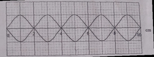
Rectilinear Propagation of waves means straight line travel of waves. It is a property that describes wave as traveling in a straight lines and perpendicular to the wavefront.
To illustrate rectilinear propagation of waves, consider the ripple tank that is set to produce plane waves.
Two rulers are placed underneath the tray of the ripple tank. They are parallel to each other and perpendicular to the bar so that the waves produced are plane waves.
Consider the setup below;
Illustrating rectlinear Propagation of waves in a ripple tank
When we start the vibrator and adjust it to the appropriate frequency, the wave fronts are perpendicular to the wavefront.
If we replace the straight bar attached to the vibrator with a small ball, the vibrator produces circular waves that propagates as illustrated below.
We can then adjust the rulers beneath the tray such that they are perpendicular to the wavefronts. We see that the circular waves moves outwards from the source and always perpendicular to the wavefronts.
From here we see that waves are propagated along straight lines.
Wavefronts
A wavefront is an imaginary line which joins a set of particles which are in phase for a wave in wave motion . While observing wave motion in a ripple tank, wavefronts can be seen on the white paper. The formation of circular wavefronts and plane wavefronts are as shown.
Circular and plane wavefronts
A ray in wave propagation
A ray is an idealized line that represents the direction of energy flow or wave propagation in a medium.
In waves, a ray is a line drawn perpendicular to the wavefront showing the direction of travel of the wave energy. See the figure below
The figure shows that the direction of wave travel is perpendicular to the direction of vibration.
This lenses operates from the principles of light refraction(bending) when the medium of transmission changes. Questions on thin lenses test several important physics concepts. These include:
1. Refraction of Light
Bending of light when it passes from one medium to another
How curved surfaces (lenses) change the direction of light rays.
Application of Snell’s Law (conceptually, even if not directly calculated).
II . Image Formation
Understanding how images are formed by:
Convex (converging) lenses
Concave (diverging) lenses
A learner must know:
When images are real or virtual
if images formed upright or inverted
Whether image formed is
magnified or diminished
III. Ray Tracing Principles
Use of the three principal rays:
Ray parallel to the principal axis
Rays through the optical centre
Ray through the focal point
This tests geometric understanding of light behavior.
iv. Lens Formula (Mathematical Relationship)
Tests:
Algebraic manipulation
Substitution and rearrangement
Use of correct sign convention
v. Magnification
M=uv
or
Tests:
Proportional reasoning
Understanding of image size relationships
vi. Graphical Skills
Some questions require:
Scale diagrams
Plotting graphs
Determining focal length from graphs
vii. Experimental Skills
Students may be tested on:
Determining focal length experimentally
Sources of error
Drawing conclusions from results
viii. Concept of Proportionality
Especially in experiments relating object distance, image distance, and focal length.
Some examination Questions on Thin Lenses
Question 1 (Thin lenses)
(a) State the meaning of the term “principal focus” as applied in thin lenses. (1 mark)
(b) you are provided with the following apparatus to determine the focal length of a lens:
-a biconvex lens and lens holder.
-a lit candle
-a white screen.
-a metre rule
(i) Draw a diagram to show how you would arrange the above apparatus to determine the focal length of the lens (1 mark)
(ii) Describe the procedure you would follow. (1 mark)
(iii) state two measurements that you would take (2 marks)
(iv) Explain how the measurements in (iii) would be used to determine the focal length. (2 marks)
(c) An object is placed 30 cm infront of a concave lens of focal length 20 cm. Determine the magnification of the image produced. (4 marks)
Question 2
(a) state 2 applications of convex lenses (2 marks)
(b) A form 4 student did an experiment on thin lenses by varying the object distance and recording the corresponding image distance for the formed by the lenses in an attempt to determine the focal length.
Object distance u (cm)
Image distance V (cm)
UV (cm2)
(U+V)cm
15
30
20
20
25
16.7
30
15
40
13.3
60
12
On the grid provided, plot the graph of uv against u+v (5 marks)
Contains information related to marketing campaigns of the user. These are shared with Google AdWords / Google Ads when the Google Ads and Google Analytics accounts are linked together.
90 days
__utma
ID used to identify users and sessions
2 years after last activity
__utmt
Used to monitor number of Google Analytics server requests
10 minutes
__utmb
Used to distinguish new sessions and visits. This cookie is set when the GA.js javascript library is loaded and there is no existing __utmb cookie. The cookie is updated every time data is sent to the Google Analytics server.
30 minutes after last activity
__utmc
Used only with old Urchin versions of Google Analytics and not with GA.js. Was used to distinguish between new sessions and visits at the end of a session.
End of session (browser)
__utmz
Contains information about the traffic source or campaign that directed user to the website. The cookie is set when the GA.js javascript is loaded and updated when data is sent to the Google Anaytics server
6 months after last activity
__utmv
Contains custom information set by the web developer via the _setCustomVar method in Google Analytics. This cookie is updated every time new data is sent to the Google Analytics server.
2 years after last activity
__utmx
Used to determine whether a user is included in an A / B or Multivariate test.
18 months
_ga
ID used to identify users
2 years
_gali
Used by Google Analytics to determine which links on a page are being clicked
30 seconds
_ga_
ID used to identify users
2 years
_gid
ID used to identify users for 24 hours after last activity
24 hours
_gat
Used to monitor number of Google Analytics server requests when using Google Tag Manager