Category: Physics

  • High Voltage Power Transmission and Power Losses

    High Voltage Power Transmission and Power Losses

    High voltage power transmission systems are designed to transport electrical power over long distances while reducing power losses caused by resistance in transmission cables. By increasing voltage and lowering current, power companies can deliver electricity more efficiently, safely, and reliably. This process plays a major role in modern power grids and helps ensure stable electricity supply across cities and rural areas.

    In this article, you will learn how high voltage power transmission works, why power losses occur during transmission, the importance of transformers in reducing energy wastage, and the dangers associated with high voltage lines. You will also explore practical examples and calculations that explain how electrical engineers minimize power loss in transmission systems.

    Whether you are a physics student, engineering learner, teacher, or simply curious about electricity transmission, this guide will help you clearly understand the science behind high voltage power transmission and power losses.

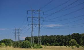
    Electricity generated at power stations must travel long distances before it reaches homes, industries, schools, and businesses. To make this possible efficiently, electrical power is transmitted using high voltage transmission lines. High voltage transmission helps reduce energy losses and ensures reliable delivery of electricity over large distances.

    High voltage power transmission flow diagram
    • Electricity is generated at power stations.
    • Voltage is stepped up for efficient long-distance transmission.
    • High voltage reduces power losses in transmission cables.
    • Substations step the voltage down before distribution to consumers such as homes, industries, schools, and businesses.

    What is High Voltage Transmission?

    High voltage transmission is the process of carrying electrical power over long distances using very high voltages such as 110 kV, 220 kV, 400 kV, or even 765 kV. Transmitting electricity at high voltage reduces the amount of energy lost as heat in the transmission cables.

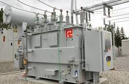
    Power stations usually generate alternating current (AC) electricity at voltages between 11 kV and 25 kV. Before the electricity is transmitted, transformers are used to step up the voltage to much higher levels, typically between 132 kV and 400 kV.

    The electricity is then transmitted through overhead power lines to substations, where the voltage is stepped down for safe distribution to consumers.

    Different consumers require different voltage levels:

    • Heavy industries may require voltages above 30 kV
    • Light industries may use around 10 kV
    • Homes and domestic users usually require 240 V
    High voltage power transmission cables
    power transmission cables

    How Power is Distributed

    The transmission and distribution process follows these stages:

    1. Electricity is generated at the power station.
    2. A transformer steps up the voltage for long-distance transmission.
    3. Electricity travels through high voltage transmission cables.
    4. Substations step down the voltage.
    5. Electricity is distributed to homes, industries, and businesses at suitable voltage levels.

    Why High Voltage Reduces Power Loss

    Electrical cables have resistance, and this resistance causes some electrical energy to be lost as heat during transmission.

    The power loss in transmission lines is given by:

    P=I2RP = I^2RP=I2R

    Where:

    • P = power loss
    • I = current flowing through the cable
    • R = resistance of the cable

    From the formula, power loss increases when current increases. Therefore, reducing current reduces energy losses.

    Since electrical power is also given by:

    P=VIP = VI

    For the same amount of power, increasing the voltage allows the current to decrease. This is why electricity is transmitted at very high voltages and low currents.

    Methods Used to Reduce Power Losses

    Power companies use several methods to minimize losses during transmission:

    1. Stepping Up Voltage

    Transformers increase the voltage before transmission. Higher voltage means lower current and therefore lower power loss.

    2. Using Thick Transmission Cables

    Thicker cables have lower resistance, which reduces heat losses.

    3. Using Good Conductors

    Transmission cables are made using materials with low electrical resistance.

    Why Aluminum is Preferred for Transmission Cables

    Aluminum is commonly used in transmission lines because:

    • It is a good conductor of electricity
    • It is lightweight
    • It is cheaper than many other conducting materials

    Dangers of High Voltage Transmission

    Although high voltage transmission is efficient, it also presents several risks:

    • Electric shock if cables fall or hang too low
    • Fires caused by loose or damaged cables
    • Strong electric fields that may affect nearby communities
    • Lightning strikes causing surges in electrical systems
    • Cables touching during strong winds and causing sparks or fires

    Proper maintenance and safety measures are therefore very important.


    Example Problem

    A transmission cable has a resistance of 100 Ω and carries electricity at 10 kV with a current of 1.0 A. The voltage is stepped up to 18 kV using a transformer.

    Determine the power loss after stepping up the voltage.

    Solution

    Assuming the transformer is 100% efficient:

    Step 1: Use the transformer power relationship

    VpIp=VsIsV_p I_p = V_s I_sVp​Ip​=Vs​Is​

    Substituting the values:

    • Primary voltage = 10,000 V
    • Primary current = 1.0 A
    • Secondary voltage = 18,000 V

    10000×1.0=18000×Is10000 \times 1.0 = 18000 \times I_s10000×1.0=18000×Is​ Is=1000018000I_s = \frac{10000}{18000}Is​=1800010000​ Is=0.556 AI_s = 0.556\ AIs​=0.556 A

    Step 2: Calculate Power Loss

    Using:P=I2RP = I^2RP=I2R P=(0.556)2×100P = (0.556)^2 \times 100P=(0.556)2×100 P30.9 WP \approx 30.9\ WP≈30.9 W

    Without Stepping Up the Voltage

    P=(1.0)2×100P = (1.0)^2 \times 100P=(1.0)2×100 P=100 WP = 100\ WP=100 W

    This shows that stepping up the voltage significantly reduces power loss.


    Practice Question

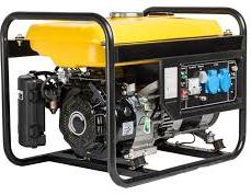
    A generator produces 750 kW at a voltage of 15 kV. The voltage is stepped up to 125 kV and transmitted through cables with a resistance of 500 Ω.

    Assuming the transformers are 100% efficient, calculate:

    1. The current produced by the generator
    2. The current flowing through the transmission cables
    3. The voltage drop across the cables
    4. The power lost during transmission
    5. The power reaching the substation

    Conclusion

    High voltage transmission is an essential part of modern electrical power systems. By transmitting electricity at high voltage and low current, power companies minimize energy losses and improve efficiency over long distances.

    Transformers play a key role in stepping voltage up for transmission and stepping it down for safe use by consumers. Despite the dangers associated with high voltage lines, proper design and maintenance make power transmission both efficient and reliable.

    Related topics

  • Simple Electric Circuits

    Simple Electric Circuits

    Electric circuits are pathways through which electric current flows. We can make simple electric circuits using simple apparatus and procedure.
    An electric current is the flow of electric charge through a conductor, such as a wire. It occurs when charged particles move. Typically, electrons respond to an electric field created by a voltage difference across the conductor. Voltage difference is provided by a cell or a battery.

    A cell is a device that converts chemical energy into electrical energy, providing a source of electrical power. It consists of one or more electrochemical reactions that generate a flow of electrons, which is the electric current. A battery is a combination of two or more cells.

    The figure below shows a dry cell that is common in making of many simple circuits.

    showing Simple Electric Circuits
    a dry cell

    The figure below three dry cells connected to make a battery:

    simple electric circuit using battery of three cells
    battery of cells

    Cell provides the energy required to pump electrons in a conductor so that they can move in a closed loop. A cell creates voltage difference by creating a region of excess electrons on one side and deficit of electrons on the other side through chemical reactions. A conductor is connected such that it runs from one side of the cell to the other in a closed loop.

    When there is no gap between the two ends of the cell or battery along the conductor, the circuit is said to be complete. Charge flows only when the circuit is complete. Cell acts as the pump to push the charges along the conductor so that they can be on the move.

    The end of battery with excess of negative charge is called the negative terminal. The other end with with deficit of charge is known as the positive charge. Charge flows from negative terminal of a cell towards the positive terminal. Current flows in opposite direction conventionally form positive terminal of the battery towards the negative end. Current is when charges flow and is a function of the speed of flow of charges. Infact the formal definition of current is that current is the rate of flow of charges. The standard international unit of current is called Ampere (A).

    From the definition of current:

    Current(I)=charge flowing through a section of conductor per unit time(t)

    I=Qt where I is the current and Q is the amount of charge flowing

    charge is measured in coulombs while time is in seconds. Therefore Ampere is the number of coulombs per second.

    Example:

    What is the current flowing through a bulb where 100 coulombs of charge is observed to flow for 1.8 minutes?

    solution

    I=Qt

    =10060×1.8=100108=0.926 A

    Example 2:

    what amount of charge is flowing through a conductor where current flowing is 6.0 A

    solution

    I=Qt=Q x 1 second

    6.0=Q x 1 second

    Q = 6.0 coulombs

    Making of Simple Electric Circuits

    A simple electric circuit consists of a few basic components arranged in a loop that allows electric current to flow. The most basic components of a simple circuit includes:

    Power Source

    This is typically a battery or a cell that provides the electrical energy to push the charge around the circuit. The positive and negative terminals of the power source create a voltage difference that drives the current.

    Conductor

    These connect the components of the circuit and provide a path for the current to flow. The most common material to make conductors is copper wires. Other useful material to make electric current is aluminum wire. other wise most of metallic materials can conduct electric current.

    Load

    A load is any component that uses electrical energy. It performs a function, such as a light bulb, motor, or resistor. The current passes through the load, and energy is transferred to it (e.g., light or heat).

    Switch

    A switch is used to control the flow of current in the circuit. When the switch is open, the circuit is incomplete, and current does not flow. When the switch is closed, the circuit is complete, and current flows.

    The simplest of electric circuit is made up battery and a conductor.

    showing simplest circuit in
    A very simple circuit made of a dry cell and a conductor

    This circuit above is simple and naive , to make a working circuit, you need to some few extra components.

    The bulb is used to show that current is flowing when the bulb lights. Opening the switch makes the bulb off showing that current off have been cut off. Current is conventionally set to flow opposite direction to the flow of charge.

    Convectional Circuit Diagram

    For clarity and neatness, symbols are used in representing components of an electric circuit. It would be tedious and clumsy to draw each of the components used in circuits. Therefore, we use symbols so that we can easily represent circuits in diagrams.

    The figure below shows the circuit that was shown above drawn in convectional ways using symbols.

    An open circuit

    On the diagram above, there is a gap on the switch. The loop from the positive terminal of the cell towards the negative one has a gap. The circuit is said to be incomplete or open. No current is flowing in such circuit and is usually referred as an open circuit.

    Switch acts like a gate, it connects two parts to make the circuit complete. When switch is closed, the circuit becomes complete. The figure below shows a complete circuit.

    table showing symbols used in simple electric circuit
    A closed circuit

    In the diagram below, current will flow from positive of the battery to the negative without encountering a gap. the bulb with thus light because it is in a closed circuit.

    While drawing or interpreting circuit diagrams, Connecting wires are drawn as straight lines with right angle corners. However, the actual wires are flexible and bent.

    The arrow-heads drawn on the lines indicates direction of the flow of current. Remember that, current flows opposite direction to that of charge flow.

    Short circuiting

    Short circuiting is a condition where an electric current is caused to flow through a path of low resistance to avoid the path with high resistance.

    Electric current usually follows a path of least resistance when moving.

    consider the figure below.

    simple electric circuit
    short circuiting a cell and a bulb

    Bulb is considered to be of much higher resistance compared to the conducting wire. In the above connection, current will flow through wire AB and avoid passing through the bulb. The bulb with thus not light and is said to be short circuited. In the figure above, both the cell and the bulb are short circuited.

    In the figure below only the bulb is short circuited.

    a short circuiting wire being connected across the bulb in a simple electric circuit
    short circuiting a bulb

    Common electrical symbols used in circuit diagrams

    each component in a circuit diagram has a unique symbol that represent it. The table below summarizes information about most of components used in circuit diagrams and their symbols.

    SymbolComponent name
    A cellcell
    battery symbol as used in simple circuitsbattery
    switch symbol used in simple circuit diagramswitch
    symbol for bulb used in simple circuitsbulb
    symbol for filament lampfilament lamp
    wires crossing without joining in simple circuitwires crossing without connecting
    Wires joining in a simple circuitwires crossing with connection
    Fixed resistor symbol used in circuit diagramsFixed resistor
    variable resistor symbol as used in simple circuit diagramsvariable resistor
    potential divider symbol used in circuit diagramspotential divider
    Rheostat symbol used in circuit diagramsrheostat
    capacitor symbol used in circuit diagramscapacitor
    fuse symbol in circuit diagramsfuse
    Ammeter symbol used in circuit diagramsAmmeter
    Voltmeter symbolvoltmeter
    Galvanometer symbolGalvanometer

    Related topics

  • Some applications of electromagnetic induction

    Some applications of electromagnetic induction

    Electromagnetic induction, the phenomenon where a changing magnetic field induces a voltage in a nearby conductor, has numerous practical applications. Some applications of electromagnetic induction include electric generators, transformers, induction cooking, and magnetic flow meters. 

    applications of electromagnetic induction: induction coil

    Induction coil is an important application of the electromagnetic induction. The induction coil consists of few turns of thick insulated copper wire wound on a primary coil. Then a secondary coil of many turns of thin insulated copper wire. we wound Both primary and secondary coil on a soft iron core. see the figure below:

    some applications of electromagnetic: induction coil

    The structure and working of the induction coil

    we connect the primary coil to a direct current source of low voltage. In the figure below , we have wound the primary and secondary coil on top of the other.

    The structure of the induction coil

    When we close the switch , the soft iron core becomes magnetised due to the current in the primary coil. This causes it to attract the soft iron armature. The moving armature armature opens the contacts and cuts off the primary current, rapidly reducing the magnetic field to zero. This induces a large a large e.m.f in the secondary coil by mutual induction. However, the spring pulls the armature back to its initial position. This action completes the circuit again in the primary circuit so that the current flow again. This process repeats itself.

    The switching on and off of the primary coil is thus continuous hence continuous changing magnetic flux. The induced e.m.f in the secondary coil is much higher when the primary coil is switching off than when switching it on. Remember the rate of current decay is usually higher than the rate of current build up in electromagnetic induction.

    Many secondary coil increases the magnitude of the induced e.m.f in the secondary coil.Spark then jumps across the gap G between the two ends of the secondary coil. Hence can be used to ignite petrol-air mixture in a car engine.

    Sparks may also occur at the contacts due to magnetic field of the primary coil. This cuts the primary coil fulfilling the Lenz’s law to keep primary current flowing.

    A capacitor connected across the contacts minimizes the sparking. This causes the primary current and hence the magnetic flux to decay smoothly to zero.

    some applications of electromagnetic induction: The moving-coil Microphone

    The moving-coil microphone is a popular application of the electromagnetic induction. A coil of wire is wound on a cylindrical former connected to a diaphragm and placed between the poles of a magnet. see the diagram below:

    some applications of electromagnetic:  The moving-coil Microphone

    Sound waves from a source sets the diaphragm in vibration. Figure below shows a typical wave profile :

    moving-microphone wave profile

    This way, it causes the coil to move to and fro, cutting the magnetic field. The field is radial so that the motion is perpendicular to it for maximum flux linkage. An induced e.m.f of varying magnitude sets up varying current in the coil. An amplifier is used to increase the amplitude of this current before it is fed into a loudspeaker. In the loudspeaker, it is converted back to sound.

    Related topics

  • An Alternating current (a.c) generator

    An Alternating current (a.c) generator

    A generator is a device that converts mechanical energy into electrical energy. It works on the principle of electromagnetic induction, where a coil of wire rotates within a magnetic field, causing an electric current to be produced. The generated electricity is then transferred through slip rings and carbon brushes to an external circuit, where it can power electrical devices such as bulbs, motors, and appliances. Generators are widely used in power stations, industries, and homes as a source of electricity.

    An Alternating current (a.c) Generator is also refereed to as the alternator. An a.c generator is a device or machine that converts mechanical energy energy into electrical energy. It does this by rotating conductors through magnetic fields.

    Working of an a.c generator

    The figure below illustrates a simple generator. It is made of curved permanent rectangular magnetic poles, slip rings, a conductor made into a loop, and carbon brushes.

    illustrating the structure of an a.c generator

    The poles of magnets are curved so that the magnetic field is radial. Current enters and leaves the coil through the brushes which are pressing against the slip rings.

    Carbon brushes are preferred because they are good conductor, slippery to allow the wire slide along with ease and acts as a lubricant. The figure illustrates a.c generator more vividly.

    Illustrating an alternating current generator

    working of an a.c Generator

    The ac generator will produce electric current in the coil when the coil rotates through magnetic field using the principle of electromagnetic induction.

    When the coil rotates clockwise as indicated on the diagram at the rotation axis, edge AB rotates upwards. Meanwhile, edge CD rotates downwards. This causes the two edges to cut the magnetic field at right angles while in the horizontal position. The induced e.m.f is maximum when the coil is perpendicular to the magnetic field.

    Determining direction of current in a.c generator

    Using the Fleming’s right-hand rule, the flow of current is in direction A-B-C-D when the direction of rotation is clockwise. The induced current flows through the external circuit via the slip rings and through carbon brushes.

    As the coil rotates from a horizontal to a vertical position, the angle at which the sides of the coil cut the magnetic field decreases. It changes from 90 to 0o. This causes the induced e.m.f to reduce from its maximum value (Eo) to zero e.m.f. when the coil becomes positioned vertically

    An overview of the cross-section of the coil in a magnetic field is shown below.

    wire rotating inside magnetic field in alternating current generator

    The coil rotates past the vertical position. At that moment, the sides AB and CD move parallel to the field. In that position, the coil does not cut the magnetic field. Therefore, the induced e.m.f is zero at that position.

    Past the vertical position, side AB and CD exchange position. Side AB starts moving downward while CD moves upward. The angle increases from 0o to 90o. This occurs as the sides of the coil cut the magnetic field and the coil returns to the horizontal position.

    When the angle is increasing from zero to 90o , the induced e.m.f increases from zero to maximum value Eo. When AB and CD exchange positions in the coil rotation, the direction of current flow reverses to D-C-B-A. This action makes brush y positive and makes brush x to be negative.

    As the coil rotates further to complete one revolution, its sides cut the magnetic field at a changing angle. This angle reduces from 90to 0o. Consequently, the e.m.f induced in the coil reduces from maximum value Eo to zero.

    induction of e.m.f in the a.c generator

    The variation of the e.m.f increases from zero to maximum at one quarter cycle. Then it reduces from maximum to zero at the next quarter circle. Next, it starts increasing to maximum value in the negative direction in the third cycle. At the fourth cycle, it increases from maximum negative value to zero. Thus, in one complete oscillation of the coil, the variation of induced e.m.f against the angle of rotation forms a sinusoidal curve. The curve formed by this variation can be represented by the equation:

    E = Eo sin θ

    where E is an instantaneous e.m.f at any particular angle of rotation where Eo is the maximum e.m.f and θ the angle between plane of the coil and the vertical axis.

    The formation of the sine curve is as illustrated

    wave equation of an a.c generator

    By ohms law;

    $$I=\frac{E}{R}$$

    where R is the resistance of the circuit and I is an instantaneous current at random position of ration of the coil.

    $$Therefore, I = \frac{E_o}{R}sin\theta$$

    A typical graph of e.m.f against the angle θ is as illustrated

    After one complete circle, the rotation pattern repeats itself and many circles are made per unit time. The number of cycles made per second is referred as the frequency of the generator and is also the frequency of the a.c current.

    Most of generators used to make commercial power productions makes 50-60 revolutions per second. In USA, the frequency is 60Hz while in Europe and Asia, it is usually 50 Hz.


    Related Topics


  • Simple electric motor

    Simple electric motor

    Simple electric motor is a device that converts electrical energy into rotational kinetic energy. A Simple d.c motor consists of a coil of insulated wire between two poles of a magnet as shown in figure below.

    The coil ABCD can turn about a fixed axis within magnetic field provided by a strong curved permanent magnet. Electric current enters the coil through split ring P and then leaves the coil through split ring Q. We refers P and Q as the commutators.

    The two half rings are insulated from each other and brushes slightly press against the commutator . We then connect the brushes to the battery terminal.

    we are assuming that the original position of the coil is at the horizontal position before the current is switched. The current flows in the direction indicated on the diagram when switch is closed. Using Fleming’s left hand rule, side AB experiences an upward force while side CD experiences a downward force.

    Simple electric motor

    Since the magnitude of current on both sides is the same, the forces on the sides are equal but opposite. The forces therefore causes the coil rotate in clockwise until it reaches it’s vertical position with side AB up. In this position, the brushes touch the space between the two halves of the split rings cutting off the current flowing hence no force is acting on the sides AB and CD at this position.

    Simple Electric motor Coil: Rotation energy

    Due to the rotational kinetic energy, the momentum in the coil carries it past this vertical position and the two split rings exchange brushes. We reverse direction of the current through the coil and consequently direction of force on each side of the coil also changes. This process is referred as commutation.

    Side AB is now on the right hand side while CD is on the left hand side. Side AB experiences a downward force while CD experience an upward force.

    The coil ABCD will continue rotating in the clockwise so long as the current is flowing through it.

    If we increase current through the coil, the coil rotates at much high speed. The speed of rotation is thus proportional to the strength of current flowing.

    If someone inter-changes terminals of the battery, the direction of the current reverses. Consequently direction of rotation of the coil reverses to the opposite direction.

    How to make Simple electric Motor more effective

    We can make the D.C motor described above more powerful by adjusting its setup in several ways that include:

    • winding the coil on a soft iron core so that iron core becomes magnetized. This concentrates it’s magnetic field in the coil which greatly increases the force on the coil.
    • Increasing the number of turns of the rotating coil. This multiplies the force on the single coil by the number of turns made.
    • using a stronger magnet that provides more powerful magnetic fields.
    • Multiplying the number of coils and commutator segments.
    • Replacing the permanent magnet by an electromagnet. This way, we adjusts strength of the magnetic field as needed.

    Related pages


    D. C motor

  • useful equations for transformers

    useful equations for transformers

    Useful equations for transformers relate voltage, current, and number of turns in the primary and secondary coils. In the equation, we assumes that the power we feed into the transformer is the same power given out. This assumption is based on another assumption that the coils of wire in the transformer is negligible.

    Electrical power = Current(I) x Voltage(V)

    power input from primary coil = Current in primary coil (Ip) x Voltage in primary coil(Vp)

    power output from secondary coil = Current in secondary(Is) x Voltage in secondary coil(Vs)

    For an ideal transformer that has no energy loss;

    Power input = power output

    that is: Ip x Vp = Is x Vs

    useful equations for transformers: The turn ratio

    From previous lessons, we learnt that the magnetic flux changes in the primary coil. This changing magnetic flux links with each turn in the secondary coil.

    transformer

    Total e.m.f in the secondary coil is the sum total of the e.m.f induced in each turn of wire in the secondary coil. The voltage produced in the secondary coil is proportional to the number of turns in that coil. The voltage changes as the number of turns changes. We show that, the secondary coil multiplies the voltage supplied from primary coil by a constant factor that is given by:

    $$\frac{\text{number of turns in secondary coil}(N_s)}{{\text{number of turns in primary coil}(N_p)}}$$

    From the above equation we can see that:

    $$\frac{\text{Secondary voltage}(V_s)}{\text{primary voltage}(V_p)} =\frac{\text{Number of turns in secondary voltage}(N_s)}{\text{Number of turns in primary voltage}(N_p)}$$

    in short form;

    $$\frac{(V_s)}{(V_p)} =\frac{(N_s)}{(N_p)}$$

    The above equation is know as the turns rule and helps determine voltage produced by a transformer.

    The useful equations for transformers

    From the equation :

    $$I_p \times \ V_p = I_s \ \times \ V_s$$

    we can obtain by rearranging the equation:

    $$\frac{I_p}{I_s} = \frac{V_s}{V_p}$$

    combining this with the turns rule equation we have:

    $$\frac{I_p}{I_s} = \frac{V_s}{V_p} = \frac{N_s}{N_p}$$

    Example 2 problems: useful equations for transformers

    A transformer is used to provide power to a 10 V lamp from an a.c mains supply of 240 V. What should be the number of turns of the secondary coil if primary coil has 1800 turns.

    solution to the problem

    This is a case of step-down transformer. The voltage from the mains needs to be reduced to 10 V needed by the lamp.

    $$\frac{V_s}{V_p} = \frac{N_s}{N_p}$$ $$hence$$ $$\frac{10}{240} = \frac{N_s}{1800}$$ $$\text{therefore:} N_s=\frac{10}{240} \ \times 1800 = 75 \ turns$$

    Example problem 2

    A power station has an output of 45KΩ at a potential difference of 10 Kv. A transformer with a primary coil of 2000 turns is used to step up the voltage to 140Kv for transmission. Assuming that there is no power losses in the transformer, calculate:

    (a) current in the primary coil

    (b) number of turns of the secondary coil

    (c) current in the secondary coil

    Example problem 3

    A power station has an output of 50Kw at a potential difference of 1000V. The voltage is stepped up to 30000Kv by transformer T1 for a transmission along a grid of resistance 2500 Ω and then stepped down to a voltage of 240V by transformer T2 at the end of grid for use in a home.

    (a) Given that the efficiency of T1 is 95% while that if T2 is 90%, find:

    (i) The power output of T1

    (ii) current in the grid

    (iii) Power loss in the grid

    (vi) input voltage of T2

    (v) the maximum power and current available for use in the home

    (b) Explain the purpose of stepping up the voltage at the power station

    Related topics


  • Exam questions on current and electricity

    Exam questions on current and electricity

    Current and electricity are core topics in physics, encompassing electric current, circuits, resistance, and the behavior of electrons. Key areas that can be tested include the nature of electric current. Another key area is Ohm’s law, Series and parallel circuits, the heating effect of electric current among others

    Questions

    1. Figure 1 shows four identical bulbs connected to a 15 volt battery whose internal is negligible.
    Diagram for Exam questions on current and electricity. Question one
    Figure 1

    Determine the reading of the voltmeter V. (2 marks).

    2. Figure 14 shows a circuit in which a battery. a switch , a bulb, resistor P, a variable resistor Q. a voltmeter V and two ammeters A1 and A2 of negligible resistance are connected.

    P has a resistance of 10 Ω. When the switch is closed A1 and A2 reads 0.10 A and the voltmeter reads 1.5 V.

    (a) Determine;. 
    (i) the current passing through P; (3 marks).

    (ii) the resistance of the bulb (2 marks).

    (b) The variable resistor Q is now adjusted so that a larger current flows through A2 .
    (i) State how this will affect the resistance of the bulb (1 mark)


    (ii) Explain your answer in (b)(i). (3 marks)


    (c) A house has one 100W bulb, two 60W bulbs and one 30W bulb. Determine the cost of having all the bulbs switched on for 70 hours,. given that the cost of electricity is 40 cents per kilowatt hour. (3 marks).
    • 3. (a) Define current stating its S.I units.               (2 mark)
     (b) A battery circulates charges round a circuit for 1.5 minutes. If the current is held at 2.5 Amperes,   what quantity of charge passes though the wire? (2 marks)


    4. Figure 2 shows arrangement of three capacities of 10µF, 2µF and 5µF.

     network three capacities of 10µF, 2µF and 5µF and a cell of 2V

    Determine the effective capacitance. (3 marks)

    5.(a) Figure 8 shows a graph of potential difference V (volts) against a current I(amperes) for a certain device.

    From the graph:

    (i) State with a reason whether or not the device obeys ohms law.    (2 marks)

    (ii) determine the resistance of the device at ;

         (I) I =1.5 A           (2 marks)

          (II) I = 3.5 A         (2 marks)

    (iii) From the results obtained in (ii) state how the resistance of the device varies as the current increases.      ( 1 mark)

    (iv) State the cause of this variation in resistance.  (1 mark)

    5(b) Three identical dry cells each of e.m.f 1.6 V are connected in series to a resistor of  11.4 ohms.  A current of 0.32A flows in the circuit. Determine:

       (i) The total e.m.f of the cells     (1 mark)

      (ii) The internal resistance of each cell;    (3 marks)

    6. Figure 6 below shows an electric generator. The points P and Q are connected to a cathode ray oscilloscope (CRO).

    exam question on electric generator:
    Figure 6

    Sketch on the axes provided the graph of the voltage output as seen on the CRO, given that when t=0 the coil is at the position shown in the figure.   (2 marks).

    7. A 60 W bulb is used continuously for 36 hours. Determine the energy consumed. Give your answer in kilowatt hour (kWh).  (3 marks)

    8. Figure 8 shows the cross-section of a dry cell. Use the information on the figure to answer questions 4 and 5.

    Figure 8

    Name the parts labelled A and B. (2 marks)

    8 (b)  State the use of the manganese(IV) oxide in the cell. (1 mark).

    9. A 4 ohms resistor is connected in series to a battery of e.m.f 6.0 V and negligible internal . Determine the power dissipated by the resistor (2 marks)

    10. State the reason why electrical power is transmitted over long distances at very high voltages .(1 mark)

    Related pages

  • Electric current and potential difference

    Electric current and potential difference

    Electric current and potential difference represents two phenomenon that depends on each other to exist in electricity concepts. An electric current is the rate of flow of charge through a conductor. Current flows when there is a potential difference between two points in a conductor. Electric current is measured in amperes by an instrument called ammeter. An ammeter is an electrical instrument used to measure the current flowing through a circuit. The ammeter is designed to be connected in series with the circuit. This ensures that the current flows through the ammeter, allowing it to accurately measure the amount of electrical current.

    There are two types of ammeters:

    Instruments used in experiments of electric current and potential difference

    • Analog Ammeter: This uses a needle or pointer to indicate the current on a scale.

    The figure below shows an analog ammeter ammeter common in school laboratories.

    An ammeter to measure Electric current
    An ammeter

    2. Digital Ammeter: This displays the current measurement on a digital screen. It provides a digital readout of the electrical current. Digital ammeter allows one to choose a scale of measurement in amperes (A), milli-amperes (mA), or micro-amperes (µA). It uses a numerical display rather than a moving needle or pointer.

    A Digital ammeter

    Electric current flows between two points in a closed path due to a potential difference between those two points. Sometimes the flowing current can be too small to me measured by an ammeter. A more sensitive instrument may therefore be required to measure small currents.

    A millimeter is an instrument used to measure current in terms of one in thousand of an ampere. A milliammeter measures current in terms of milli-amperes.

    $$1 \ milli-ampere(MA) = \frac{1}{1000} Amperes$$

    Much smaller currents can be measured by a micro- ammeter. A micro-ammeter measures current in terms of micro-ampere.

    $$1 \ micro-ampere(\mu A)= \frac{1}{1000000} \ amperes $$

    experiments of electric current and potential difference: A micro-ammeter to measure very small electric currents and a milli-ammeter to measure relatively small currents.
    A micro-ammeter

    Using an ammeter in measuring electric current

    An ammeter has very low electrical resistance. Therefore it is connected in series with the instrument whose current passing through need to be measured. When connecting an ammeter in the circuit, ensure it is done correctly. The correct procedure is such that current enters the ammeter through positive terminal and exits through the negative terminal. If connected such that convectional current enters through negative terminal, the ammeter may get damaged.

    The figure below shows the ammeter connected in series with the bulb. The convectional current flowing through the bulb also flows through the ammeter.

    Ammeter connected in series with a bulb in experiments of electric current and potential difference
    correct ammeter connection

    The figure below shows wrong ammeter connection. Note that the positive terminal of the ammeter is connected to the negative terminal of the cell.

    wrong ammeter connection

    Before connecting the ammeter in a circuit, confirm that it’s pointer is at zero mark on the scale. Otherwise, use the zero adjusting screw to move it to the correct position. Most of ammeters has two scales. An appropriate scale should be selected to safeguard the coil from damaged if current passing exceeds its capacity. For example an ammeter can have a scale of (0-3)A or (0-5)A. The figure below shows an ammeter dashboard with two scales; (0-5)A and (0-2.5)A.

    Ammeter reading with two scales

    If a scale of (0 – 5) A is selected, the meter can read up to 5 A. With such a scale, 10 divisions represents 1.0 A. For a (0-2.5) A scale, ten divisions will represent 0.5 A meaning each division is 0.05 A. From the diagram, the reading on the ammeter is 2.45 A while reading (0-5) A or 1.225 while reading the (0 -2.5) A.

    Electric current and potential difference: using a voltmeter

    while investigating electric current and potential difference, we need to measure potential difference across various components in the circuit. A voltmeter is always connected across the device (parallel to the device) which the voltage is to be measured. The figure below shows voltmeter connected across the bulb in parallel arrangement.

    circuit diagrams showing how to connect voltmeter while measuring potential difference across the bulb

    Voltmeter is connected in series because it is an instrument with high resistance to the flow of current. Therefore, It takes no current from the component across which the voltage is to be measured.

    The positive terminal of the voltmeter is connected to the point where convectional current is entering a component. Its negative terminal is connected to the point where the current is leaving the component.

    One should ensure that the pointer is exactly on the zero mark before connecting the voltmeter. If pointer is not at zero, the pointer should be adjusted to zero by the screw.

    potential difference

    Work must be done to move an electric charge through a conductor. The device that produces energy to do this work is called a source of electromotive force (e.m.f). The source may be a battery, which converts chemical energy to electrical energy, or a generator, which converts mechanical energy to electrical energy. When the battery does the work of pumping charges through a conductor or an electrical device, an electrical potential difference(p.d) develops between its end. This potential difference is measured in volts using the voltmeter.

    Potential Difference and the Voltmeter

    A lack of “pumping” charges through a conductor indicates that there is no potential difference between two points. The potential difference (p.d) between two points A and B (Vab)of a conductor is defined as the work done in moving a unit charge from point B to A.

    in other words:

    $$\text{Potential difference} = \frac{\text{work done W(in joules)}}{\text{charge moved Q (in coulombs)}}$$
    $$V_{AB} = \frac{W}{Q}$$

    where: (VAB) = potential difference across AB.

    • (W) = work done (in joules)
    • (Q) = charge moved (in coulombs)

    From the equation, one volt is equal to one joule per coulomb.

    Measuring potential difference

    The voltmeter measures potential difference. In laboratories, moving coil voltmeters are commonly used, although today many of these instruments are replaced by digital voltmeters.

    (a) Analogue voltmeter
    (b) Digital voltmeter

    Please note that instruments like fuel gauge and speedometers are essentially voltmeters.

    Example

    In moving a charge of 10 coulombs from point B to point A, 120 joules of work is done. What is the potential difference between A and B?

    solution:

    $$p.d = \frac{W}{Q} = \frac{120}{10} = 12V$$

    Using a Voltmeter

    A voltmeter is always connected across (in parallel to) the device whose voltage is to be measured. consider the diagram below.

    Voltmeter connected across the bulb
    lab setup for bulb connected across the battery

    Because the voltmeter has a high resistance to the flow of current, it draws very little current from the component.

    The positive terminal of the voltmeter is connected to the point where conventional current enters the component, while the negative terminal is connected to the point where the current leaves the component.


    Experiment To Investigate the Current and Voltage in a Parallel Circuit Arrangement

    Apparatus

    • Two 1.5 V cells
    • 3 identical bulbs
    • 3 ammeters
    • 4 voltmeters
    • Switch
    • Connecting wires

    Procedure

    • Connect the circuit as shown in figure below.
    Current and Voltage in Parallel
    • Switch on the circuit and take the readings on the ammeters A1, A2,A3 and A4.
    • Switch off the circuit and disconnect the ammeters.
    • Connect the bulbs and the voltmeters as shown in figure
    • Take the readings on V1,V2,V3 and V4.

    Observation

    1. Reading on A1 = Reading on A2 + Reading on A3 = Reading on A4
    2. Reading on V1 = Reading on V2 = Reading on V3 = Reading on V4.

    Conclusion

    When components are connected in parallel:

    1. The sum of the currents in parallel circuits is equal to the total current. The total current entering a junction equals the total current flowing out.
    2. The same voltage drops across each of the components.

    Example 2

    Find the current passing through L1 in figure below, given that 0.8 A passes through the battery, 0.28 A through L2, and 0.15 A through L3.

    Solution

    Current through battery = Current through L1 + Current through L2 + Current through L3

    0.8 = I1+I2+I3

    0.8=I1 + 0.28+0.15

    0.8 =I1 + 0.43

    Therefore:

    I1 = 0.8A – 0.43A = 0.37A

    Experiment To Investigate Current and Voltage in Series Arrangement

    Apparatus

    • 4 voltmeters
    • 3 torch bulbs (2.8 V)
    • Bulb holder
    • Switch
    • Connecting wires
    • Two cells

    Procedure

    • Connect the circuit as shown in figure below
    bulbs in series
    • Switch on the circuit and record the readings on the meters.
    • Switch off the circuit and disconnect the ammeter.
    • Connect the bulbs, ammeter, and voltmeters as shown in figure below.
    • Switch on the circuit and record the readings on the meters.
    observations

    The reading of current by the ammeters A1 and A2 and A3 is the same.

    The total voltage drops across the bulbs (V1+v2+v3) equals to the total voltage v4 across the terminals of the battery.

    please note that the observations will remain true even when the bulbs are not identical.

    conclusions

    In a series arrangement, the same current flows through each component.

    The sum of the voltage drops across the components is equal to supply voltage


    Summary

    • A voltmeter measures potential difference.
    • Potential difference is the work done per unit charge.
    • Voltmeters are connected in parallel across components.
    • In parallel circuits, current splits while voltage remains the same.
    • In series circuits, current remains the same throughout the circuit.

    Related Topics


  • Examination Questions on measurements

    Examination Questions on measurements

    Examination questions on measurements basically covers concepts like:

    •  Length and Distance
    • Weight and Mass
    • Basic Units and Conversions
    •  Volume and Capacity
    • Time
    • Temperature
    • Derived Units and Calculations
    •  Measuring Instruments
    • Precision and Accuracy

    Here are the questions that involves measurements

    1. The diagram below shows a piece of wood whose length is being measured using a strip of           measuring tape.


                What is the length of the piece of wood.

    2. Figure 1 below shows a Vernier calipers being used to measure the thickness of an object. It has a error of +0.01 cm.

    What is the correct measurement?                                                                       (2 marks)

    3. Figure  below shows  Perspex  container  with a square base  of side  5 cm . It is carrying  water  to a height  of 7 cm.

    When pebble is immersed  into  the water, the level  rise  to 10 cm. what is  the volume of the pebble? (2 marks)

    4.   A  drop  of  oil volume  6 x 10 -9 m3 forms  a patch  of area  0.0755 m2  on a water  surface. Estimate the of an oil  molecule ( 2 marks).

    Related topics

  • Exam questions on thin lenses

    Exam questions on thin lenses

    Exam questions on thin lenses often cover the properties of converging (convex) and diverging (concave) lenses. These questions include topics like image formation, focal length, magnification, and the thin lens equation. 

    You face questions asking you to define key terms. They ask you to distinguish between real and virtual images. You can also be asked to apply the thin lens formula to calculate image distances, focal lengths, or magnification. Additionally, questions involve ray diagrams, understanding how lenses correct vision defects, or comparing lenses with mirrors. 

    Here’s a breakdown of common question types:

    • Definitions and Concepts
    • Image Formation
    • Thin Lens Equation and Calculations
    • Applications and Comparisons
    • higher order questions live derivation of equation

    Examination Questions on thin lenses

    1. Figure 10 below shows an object in front of a lens.

    (i) Using rays locate the image of the object as seen by observer E.

    (ii)Give one application of such a lens as used above.

    (iii) Write three similarities between an eye and a camera

    ( b)   Figure 11 (a) and (b) show diagram the human eye

    In figure 11 (a) sketch array diagram showing long sightedness

    And In figure 11 (b) sketch array diagram showing how a lens is used to correct the long sightedness.

    (c) A object of height 10.5 cm stands before a diverging lens of focal length 20 cm and a distance of 10cm from the lens. Find.

    i)          Image distance

    ii)         Height of the image

    iii)        Magnification

    2. A real object of height 1 cm placed 50 mm from a converging lens. It forms a virtual image 100 mm from the lens.

    (i) Determine the:

    (I) focal length of the lens ; (3 marks)

    (II) magnification. (2 marks)

    (ii) On the grid provided, draw to scale the ray diagram for the setup to show how the image is formed (3 marks)

    3. Figure 8 shows an object O placed in front of a diverging lens whose principal focus is F.

    Figure 8

    on the figure , draw a ray diagram to locate the image formed (3 marks)

    Question 4

    17 (a) Figure 16 shows a graph of magnification against object distance for an object placed in front of a lens of focal length 20 cm.

    Using the graph;

    (i) State the effect on the size of the image when the object distance is increased from 25 cm. (1 mark)

    (ii) Determine the distance between the object and the lens when the image is the same size as the object (2 marks)

    (iii) Determine the image distance when the object distance is 25 cm. (3 marks)

    Related topics