The degree to which a lens deviate light is called the optical power.
Optical power measures how sharp the lens bends light that passes through it . Optical power P is given by P=1/f where f is the focal length of the lens. From the equation, one can see that the shorter the focal length, the higher the optical power. The unit for optical power is m-1 .
m-1 is known as dioptre (D)
Len’s Combination
If an object is placed infront of a combination of two or more lenses, it’s image in the first lens becomes the object for the second lens which in turn produces another image. If there is a third lens, the second image becomes it’s object.
One application of the Len’s combination is the compound microscope which combines two converging lenses of short focal length. In the microscope, the lens near the object is known as the objective lens and one near the eye is referred to as the eyepiece. Eyepiece has longer focal length compared to objective lens.
Compound microscope structure
The object to be viewed is placed between Fo and 2Fo of the objective lens so that a real inverted and magnified image is formed. This image is infront of the eyepiece and will act as an object to it. The eyepiece is adjusted so that this image falls between it’s principal focus Fo and itself so that a virtual but magnified image is obtained. The eyepiece therefore acts as a magnifying glass and produces a final image that is greatly magnified as in the figure above
Compound Microscope magnification
Magnification of objective lens mo = u/v where v is the distance of the first image from the objective lens and u the object distance. Taking fo as the focal length of the object lens, then from the lens formula:
1/v + 1/u = 1/fo
multiplying through by v;
1 + v/u = v/fo
substituting mo = u/v; we have
1 + mo = v/fo and so mo = v/fo -1
similarly, magnification me produced by the eyepiece will be given as:
me = D/fe -1
where D is the distance of first image from the lens.
Total magnification produced by this lens arrangement is the product of mo and me
That is, Total magnification = ( D/fe -1)(v/fo -1 )
Oxford English dictionary describes force as strength or energy as an attribute of physical action or movement.
A force acts acts in a particular direction and have the following effects:
Effects of force
(i) change the state of motion of a body.
A body that is not moving can be set in motion when a force is applied on it and a moving body will stop when force is applied against it the opposite direction to it’s motion.
a moving body can increase its speed if a force is a applied on it in the direction of it’s motion and it’s motion can be reduced when an opposing force is acting against it’s motion. For example friction force reduces motion of an object dragged on a flat surface.
(ii) Distorts or changes shape of an object.
For example a force applied on a glass causes it to crack. When force is applied on an elastic material, it expands. A plastic bottle will change shape when force is applied on it. Similarly, a car that meet with an accident will have a bad shape.
distorted car after an accident
(iii) causes object to turn or changes direction.
when a force is applied on one end of the object when it is fixed from another point, the body tends to change direction. The change of direction from a fixed point is usually referred to as the turning effect of force. The figure below illustrates a spanner that turns about a fixed point in order to tighten or loose a nut.
spanner at work
Describing force
Force is also described as the source of energy which changes body’s state of motion, direction or shape. Large forces causes large effects on bodies and small forces has less significant effects on bodies.
Force always acts towards specific direction and so it is a vector quantity as it has both magnitude and direction
Force in diagrams is represented by a line with an arrow showing the direction in which it acts.
Electromagnetic waves are usually detected by devices or gadgets. The human eye can only detect only a small portion of this spectrum called visible light. A radio detects a different portion of the spectrum, and an x-ray machine uses yet another portion.
Gamma Rays
Detected by photographic plates and radiation detectors like Geiger Muller Tubes.
we need a gamma spectrometer to know the energy ranges of the γ photons emitted by a radioactive source. A gamma spectrometer generally consists of a scintillation detector or a semiconductor detector to convert the γ rays into visible light or electronic signals respectively. With a multi-channel analyser, a gamma spectrum depicting the number distribution of γ photons at different energy ranges can be obtained. The γ spectrum is like the “fingerprints” of nuclides which facilitate the identification of different nuclides in a radioactive source.
By counting the rate of charge pulses or voltage pulses or measuring the scintillation of the light emitted, the number and energy of gamma ray photon striking an ionisation detector or scintillation counter can be found.
Gamma spectrometer circuit
X-rays Detection
In X-ray detectors the energy transported by the radiation is converted into forms that can be recognized visually or electronically. Generally the photons are absorbed by the detector material and energy transfer takes place by ionization.
X-rays are usually detected by using a fluorescent screen or photographic film.
In hospitals, X-rays used to observe broken bones are detected by their actions on specially designed photographic emulsions. This high energy radiation may also be detected by its ability to ionise gas atoms producing a pulse of electric current in a gas placed between two electrodes.
Geiger Muller counter using the ionisation of gas atoms detects the presence of both X-rays and gamma rays.
X-ray detector
Detection of Ultraviolet Radiation
It is usually detected by photographic films, photocells, fluorescent materials like quinine and sulphate and a paper slightly smeared with vaseline.
Quinine, a substance found in tonic water is sensitive to UV light and can absorb UV light that we can’t see and then re-emit visible blue light that we can see in a process known as fluorescence
A fluorescent material is one that absorbs the energy of UltraViolet light and then re-emits it as visible light.
The inner surface of a fluorescent tube is coated with a fluorescent material .The tube is filled with a gas that emits UV light when made to conduct by a high voltage.
fluorescent lamps
Visible light
Common detectors of visible light are the eye, photographic film, charge-coupled devices (CCDs) and the photocell.
Photographic films detects light by the chemical changes it produces in light-sensitive chemicals such as silver halides. Light is also detected by the photoelectric effect in which its energy causes electrons to be emitted from metal surfaces.
By use of photoelectric effect, electrons are collected in a photomultiplier tube and the current they produce amplified to produce an electric signal.
Semiconductors are used to produce photovoltaic cells which generate a current when light falls on them and photoresistors in which incident light causes a change in electrical resistance.
visible light detectors
Detecting Infrared Radiation
It is usually detected by the heating effect produced on the skin, a thermopile, bolometer and thermometer with a blackened bulb.
A bolometer contains a blackened metal strip whose temperature rises when infrared radiations falls on it and this temperature is detected by measuring the change in electrical resistance of the strip.
When infrared radiation falls on semiconductor surface, it may produce an electromotive force(e.m.f) which decreases the electrical resistance of the material.
Photographic films sensitive to infrared radiations can be used to take infrared pictures that reveals hotspots in the landscape.
Infrared detector circuit
Microwaves detections
Microwaves are detected by crystal detectors or solid state diodes. The energy of these wave bands is absorbed by conduction electrons in metals causing electrons to vibrate in the same frequencies as the waves.
Microwave Detector Probe
Radio waves Detectors
Radio waves are detected by aerials or antennae. The energy of radio wave bands is absorbed by the conduction electrons in metals causing the electrons to vibrate at the same frequencies as the waves. The resulting alternating current can be amplified electronically to produce an electrical signals with the same pattern as the radio waves. For maximum sensitivity, the size of the antennae should be of the same order as the wavelength of the radio waves.
An accelerating charged particle produces an electromagnetic (EM) wave. Electromagnetic waves are electric and magnetic fields traveling through empty space with the speed of light c. A charged particle oscillating about an equilibrium position is an accelerating charged particle and if its frequency of oscillation is f, then it produces an electromagnetic wave with frequency f.
Electromagnetic waves transport energy through space which can be delivered to charged particles a large distance away from the source.
Accelerating charges produce changing electric and magnetic fields. Changing electric fields produce magnetic fields and changing magnetic fields produce electric fields. This interplay between induced electric and magnetic fields leads to propagating electromagnetic waves through free space.
Gamma (γ) rays
Gamma rays have the smallest wavelengths and the most energy of any wave in the electromagnetic spectrum.
They results from energy changes occurring in the nuclei of the radioactive atoms.
The term gamma ray was coined by British physicist Ernest Rutherford in 1903 following early studies of the emissions of radioactive nuclei.
They are produced by the hottest and most energetic objects in the universe, such as neutron stars and pulsars, supernova explosions, and regions around black holes.
On Earth they are generated by nuclear explosions, lightning, and radioactive decay.
X-rays
They are produced when a high energy electrons bombard a metal target in an X-ray tube. They are also said to originate from fast moving electrons when they are suddenly stopped by a metal target.
Ultraviolet(UV) Radiation
They are produced by the sun, sparks and mercury vapour lamps due to large energy changes in the electrons of an atom. UV radiation is produced either by heating a body to an incandescent temperature, as is the case with solar UV, or by passing an electric current through a gas, usually vaporized mercury. Electrons in the mercury atoms gain energy from the current then emit it again as UV.
Mercury vapour lamps
Visible light
A visible light stimulus is electromagnetic radiation that can be perceived visually by an organism(Royal Society of chemistry).
Visible light is composed of seven different colours with violet having the least wavelength and red having the highest. It is naturally produced by sun, hot objects, lamps,candles, electric bulbs, laser beams e.t.c.
Visible light is created the same way all other ElectroMagnetic waves are produced from emission of radiation while an electron jumps from an higher energy state to a lower one. In this process all shorts of EM waves are created but we can see only the visible light spectrum.
Illustrating visible light
Infrared Radiation(IR)
It is produced as a result of small energy changes of an electron in an atom or molecular vibrations which happens in the sun, fire or any hot objects.
Any material with temperature above absolute zero emits InfraRed and so IR radiations are produced in all matter by means molecular vibration. Molecular movement causes infrared emission of different wavelengths and frequencies but each wave is proportional to the temperature of the body where higher the temperatures produces radiations of higher frequency and hence with shorter wavelengths.
Microwaves
They are produced by special vacuum tubes called magnetrons in microwave ovens or with a maser that operates on the ballistic motion of electrons controlled by magnetic or electric fields
Microwaves are produced by special vacuum tubes like the klystron, magnetron and Gunn diode where the frequency of microwaves is selected to match the resonant frequency of motor wall so that the energy is transferred efficiently to the kinetic energy of the molecules.
Microwave production
Radio Waves
Radio waves are produced artificially by time-varying electric currents, consisting of electrons flowing back and forth in a specially-shaped metal conductor called an antenna. An electronic device called a radio transmitter applies oscillating electric current to the antenna, and the antenna radiates the power as radio waves.
Radio waves are received by another antenna attached to a radio receiver. When radio waves strike the receiving antenna they push the electrons in the metal back and forth creating tiny oscillating currents which are detected by the receiver. see the illustrations below
I value freedom. Colonized nations fought for freedom and citizens in democratic nations pride themselves in some kind of freedom.
But you can have freedom but still not free. You can have freedom to do one thing but lack it in something else.
When we say we are free, are we free indeed.?
Types of freedom includes
Financial freedom
This is when we have enough money so that nothing that requires money that we can be restricted from. It is freedom to have whatever we desire because we can be can afford it. You may not be in prison walls but you are life is soo restricted because of being broke or poor. You cannot move even though you have freedom to move whenever you many want because you lack resources to do that. Financial freedom keeps people from attaining their desires just like people locked behind bars crave for freedom. I remember in my days of small beginnings how I desired to join some schools and get education but all I could have are desires, I could just watch the institutions walls from a distance but could not go there because I was poor. I was a prisoner of desires I could never attain just the way prisoners look at people with freedom of movement but cannot go anywhere because they are locked.
Other types of freedom includes:
Speech freedom
This is a privilege enjoyed by citizens of democratic societies or nations where they can express their thoughts and opinions without being judged harshly
Physical freedom
This is where we are not restricted in movement and we can travel or go where we need to go . But I think physical freedom is connected to financial freedom because without money you can only be able to go to only limited places.
Spiritual freedom
It is when you have peace in your soul and you are not haunted by things like guilt, anxiety or tormented by things beyond your control
Mental freedom
Ability to think clearly and have clarity of thoughts. It is where you have power to imagine and have the means to test your thoughts.
Political freedom
Ability to express your political views without intimidation , coercion or persuasion.
Academic freedom
Protection from undue influence or pressure from academic institutions, governments, or external organizations that may seek to limit or control academic inquiry and expression.
However If you have financial freedom, you can be able to purchase physical freedom as well ,,,so I think …….🤔
The electromagnetic (EM) spectrum is the range of all types of Electromagnetic radiation. Radiation is energy that travels and spreads out as it goes – the visible light that comes from a lamp in your house and the radio waves that come from a radio station are two types of electromagnetic radiation.
Electromagnetic waves are transverse waves which results from oscillating electric and magnetic fields at right angles to each other.
When all the electromagnetic spectrum are arranged in order of their wavelength or frequency, they form what is refered to as the electromagnetic spectrum.
A complete spectrum is shown below:
The figure below shows electromagnetic waves arranged in order of decreasing wavelengths
Properties of Electromagnetic waves
Electromagnetic waves have the following common properties.
They travel through vacuum(space) with a speed of 3.0 x 10⁻⁸ms-1 . This speed is usually refered to as the speed of light in vacuum and is usually denoted by c.
They do not require material medium for transmission
They are transverse in nature
They undergo interference, reflection,refraction and polarisation effect
They posses energy in different amounts according to the relation E=hf where h is the Plank’s constant given as 6.63 x 10⁻³⁴ Js and f is the frequency
They carry no charge
They are not affected by electric or magnetic fields
Example: calculating energy of a wave
A certain electromagnetic radiation was found to be having a wavelength of 6.5 x 10⁻⁸ m. Calculate the energy it emits.
solution
to calculate energy of a wave, you need to know about it’s frequency and then multiply the frequency with the planck’s constant.
we have only the wavelength only but we can get the frequency from the relation: v = fλ
since it is an electromagnetic wave, it’s speed is 3.0 x 10⁻⁸ ms-1. and hence f=v/λ. that is:
=4.6154 x 10¹⁵ HZ
The energy of a wave was defined as E = hf where h (plank’s constant)= 6.63×10⁻³⁴ Js
hence E = 6.63 x 10-34 Js x 4.6154 x 1015 HZ≈ 3.06 x 10⁻²⁰J
Mutual induction is a phenomenon in physics where a changing magnetic field in one coil of wire induces a voltage across another nearby coil. When the magnetic field passing through one coil changes, it induces a voltage in the other coil, according to Faraday’s law of electromagnetic induction.
This principle is fundamental to the operation of transformers, where two or more coils of wire are used to transfer electrical energy from one circuit to another by means of a changing magnetic field.
Mutual induction is a key concept in the functioning of many electrical devices and is utilized in various applications, including power transmission, signal coupling, and wireless power transfer.
Demonstrating mutual Induction
To investigate mutual induction, set two coils close to each other as shown
Using the variable resistor, put the current to minimum and observe the behavior on the galvanometer from the following actions:
closing the switch K
opening the switch K
Increasing the current using variable resistor when the switch is closed
decrease the current using variable resistor when the switch is closed
replace the D.C power supply with A.C power supply.
Observations
when the switch K is closed, the pointer deflects in one direction and then comes back to zero. When K is opened, the pointer deflects to the opposite direction and then falls back to zero.
Increasing current in the primary coil causes deflection while decreasing it causes deflection to the opposite direction.
If direct current (d.c) is replaced with an alternating current source, the pointer of the galvanometer vibrates continously about the zero point.
Explanations
When the switch is closed, the current in the primary coil increases from zero to maximum value within a very short time and so the magnetic flux in the primary coil linking with the secondary coil increases from zero to maximum at the same interval of time inducing an e.m.f in the secondary coil.
The induced emf in the secondary coil causes flow of current hence deflection on the galvanometer.
The induced e.m.f lasts only for a period where current is transiting from zero to maximum and so the pointer on the galvanometer returns to zero after a very short time. This is because after the current in primary coil builds up to it’s maximum value, there is no further change in magnetic flux in the primary coil and so induced e.m.f in the secondary coil stops.
When the switch is opened, the current in the primary coil takes a very short time to fall from maximum to zero hence the magnetic flux in the primary coil linking with the secondary coil also falls from maximum value to zero inducing an e.m.f in the secondary.
The current in the circuit takes much shorter time to fall off from maximum to zero than it takes to build up from zero to maximum and therefore induced e.m.f is much higher when current is being switched off than when it is switched on.
When the current is increased continously, the magnetic flux in the primary coil which links with the secondary coil also increases at the same rate causing an e.m.f to be induced in the secondary.
When current in the primary is decreased continously, an e.m.f is induced in the secondary due to the decreasing magnetic flux of the primary coil linking with the secondary coil
The direction of current in the secondary coil is to the opposite direction to that of primary coil so that the polarities in the secondary and primary coil are such that they oppose each other. The direction of current on each coil can be determined by Lenz’s law.
When the switch is closed and current is building up, the direction of current in primary and secondary coil is as illustrated below:
when the current is decaying after switch is opened, the direction of the induced e.m.f in the secondary coil is as shown.
most often the e.m.f induced in the secondary coil is less than what was produced in the primary coil. This is mostly because of what is called flux leakage where all the magnetic flux from primary coil does not link with the secondary coil.
The induced e.m.f in the secondary coil can be increased by ensuring more flux from primary coil are linking with the secondary coil.Some of the techniques used includes:
i. Winding primary and secondary coil on a soft magnetic flux
In this method, the primary and secondary coil are linked together on one soft iron which helps to concentrate magnetic flux in both coils. Typical arrangement is as shown.
In the above arrangement, both primary and secondary coil are wound on the same iron core.
ii. Both secondary and primary coil on same soft iron ring
Magnetic flux tends to form circular loop and so a circular ring makes them work better . The arrangements is as illustrated.
The ring enables all the magnetic flux of the primary to form concentric loops within it thus reaching the secondary coil more efficiently.
iii. Having more turns in the secondary coil
we saw earlier that the total induced e.m.f in the coil is the summation of all the e.m.fs induced by individual turns in the coil. When there are more turns in a coil, it then means there will be more e.m.f in that coil. Consider the setup illustrated below.
The e.m.f is induced in each turn of the secondary coil since the magnetic flux of the primary coil links with each .
The mirror describes the relationship that exists between the focal length, image distance and the object distance. By use of mirror formula that had been derived earlier, the unknown focal length of a lens can be determined experimentally. We describe the experiment here and explains how to extract the the focal length from the relationship.
Apparatus
Metre rule
lens and a lens holder
source of light
screen
cardboard with a cross wire
procedure
set the apparatus as shown
You place the object at the zero centimetre mark
set the object distance by placing the lens at a reasonable distance from the object like 80cm from the object.
Adjust the screen until a sharp image is obtained
Record a distance between the screen and the lens when a sharp image is formed on the screen. That is the image distance.
Record the image and the object distance
Reduce the object distance u by about 5 cm and then adjust the screen until another sharp image is formed on the screen.
reduce the distances distance again by 5 cm and repeat the procedure above.
Fill the table as shown below
From the data obtained, a graph of 1/u against 1/v can be plotted.
A typical graph will be as shown:
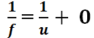
Now the lens formula is stated as:
at the (1/v) intercept, the value of (1/u)= 0
hence :
and hence
and therefore the value of f-1 (1/f) is equal to 1/v.
similarly at the (1/u) intercept, the the value of (1/v) =0
and so the lens formula becomes
hence
from the graph, we can deduce that 1/u and 1/v gives 1/f at the intercepts.
we can get two values of f from the 1/v and 1/u intercepts such that:
f1 = (1/v)-1 and f2 = (1/u)-1
the focal length f is thus the average of f1 and f2 such that
Experiments have shown that magnetic fields created by a current moving through a straight conductor forms concentric circles around the conductor. See the illustrations in figure below.
To investigate the magnetic field patterns due to a straight conductor, you may need to set up apparatus similar to the following diagram.
A card with a small hole at the center is held horizontally so that a conductor in a complete circuit is held vertically through the hole such that the cardboard and the wire are perpendicular to each other.
Iron fillings are sprinkled on the cardboard and then disturbed gently after the switch is closed. when the iron fillings are allowed to settle after disturbance, they settle around the current carrying conductor as in a pattern close to the illustrations shown shown.
if we are to represent that on a diagram, it should be circles around the conductor as shown.
This shows that iron fillings settles in concentric circles around the conductor becoming less significant ast the distance from the conductor increases from the center of the circle horizontally.
Drawing magnetic patterns using a compass.
All you need is to remove the iron fillings from the cardboard . Simply open the circuit and collect the iron fillings from the card and then leave the setup as before but with a compass on the cardboard as in figure below.
After closing the switch, note the direction of the compass needle. Now put a dot at the end of the needle and move the compass to start at the end and then make a dot at the end of the needle. Move the compass so that it’s position begins at the dot and repeat the same procedure until you have circumnavigated the wire to make the pattern as shown.
You can repeat the above procedure by selecting another radius from the conductor and trace the compass needle pattern to see it’s pattern of turning as it moves around the conductor.
observations
The compass needle are aligned in a circle pointing in the clockwise direction as in the setup described above in all radius selected to study the pattern.
If the direction of current was reversed by changing the battery polarity, the circles would be plotted pointing anticlockwise direction.
Explanations
Magnetic fields produced by a straight current carrying conductor forms a pattern of concentric circles around the conductor.
The direction of the magnetic field produced by a straight current carrying conductor can be predicted by use of Fleming’s-Right hand grip rule which states that:
If a conductor carrying current is grasped in the right hand with the thumb pointing along the wire in the direction of the convection current, then the fingers will encircle the conductor in the direction of the magnetic field.
Use of Fleming’s Right-hand grip rule is illustrated below
illustrating Fleming’s Right-hand grip rule
Direction of the magnetic field around straight conductor can also be determined by use of Maxwell’s corkscrew rule which states that:
If a right-handed screw is driven forward in the direction of the conventional current , then the direction of the rotation of the screw is the direction of the field lines.
The figure below illustrated Maxwell’s corkscrew rule:
when using the Maxwell’s corkscrew rule, you imagine fastening the screw if the current is getting in to paper and you imagine removing the screw when current is moving out of the paper.
To investigate direction of current on the straight conductor AB, you can do the following:
Move the condutor to cut the magnetic fields vertically upwards and note the direction of the magnetic field.
Move the condutor to cut the magnetic fields vertically downwards wards and note the direction of the magnetic field.
Hold the wire stationary in the magnetic field and note the deflection
Observations
when the wire is moved upwards, the deflection on the galvanometer goes right showing that the current is flowing from A to B. To represent that on a paper, the induced current is envisioned to be moving into the page away from the eye as in the following illustration.
when moved and when the wire is moved downwards deflections goes left showing that the current is moving from A to B . The current flow can be represented on a paper with current fl0wing out of the page towards the eye as in figure below.
Fleming’s Right-hand rule
Direction of an induced current in a straight conductor can be determined by Fleming’s right-hand rule which states that:
If the thumb and the first two fingers of the right hand are held mutually at right angles with the first finger pointing in the direction of the magnetic field and the thumb pointing in the direction of motion, then the second finger points in the direction of the induced current.
The figure below shows how your right hand should be held to determine the direction of the induced current by use of Flemings’s right hand rule.
Fleming’s right hand rule is also known as the dynamo rule and it agrees with the Lenz’s law.
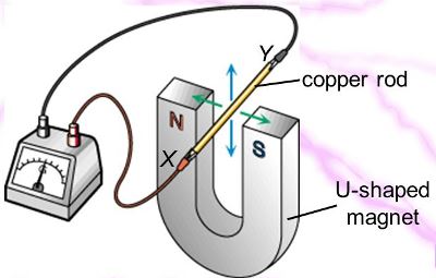
Consider a horizontal magnet held as shown in figure below:
The direction of the magnetic field is downward. The downward direction of the above magnetic field can be represent by a section of an arrow tail to show that the magnetic field is going down into the paper.
Suppose we have a conductor that is held horizontally between the two poles, the conductor will slide away or towards the magnet if it has some current flowing in it.
The figure below shows current through a certain conductor XY inside a magnetic field moving into the paper and the likely motion for such a setup.
According to Fleming’s rule which is consistent with the lenz’s law, the current must flow from X to Y in order to produce an electromotive force that is to push the rod XY to the right.
Contains information related to marketing campaigns of the user. These are shared with Google AdWords / Google Ads when the Google Ads and Google Analytics accounts are linked together.
90 days
__utma
ID used to identify users and sessions
2 years after last activity
__utmt
Used to monitor number of Google Analytics server requests
10 minutes
__utmb
Used to distinguish new sessions and visits. This cookie is set when the GA.js javascript library is loaded and there is no existing __utmb cookie. The cookie is updated every time data is sent to the Google Analytics server.
30 minutes after last activity
__utmc
Used only with old Urchin versions of Google Analytics and not with GA.js. Was used to distinguish between new sessions and visits at the end of a session.
End of session (browser)
__utmz
Contains information about the traffic source or campaign that directed user to the website. The cookie is set when the GA.js javascript is loaded and updated when data is sent to the Google Anaytics server
6 months after last activity
__utmv
Contains custom information set by the web developer via the _setCustomVar method in Google Analytics. This cookie is updated every time new data is sent to the Google Analytics server.
2 years after last activity
__utmx
Used to determine whether a user is included in an A / B or Multivariate test.
18 months
_ga
ID used to identify users
2 years
_gali
Used by Google Analytics to determine which links on a page are being clicked
30 seconds
_ga_
ID used to identify users
2 years
_gid
ID used to identify users for 24 hours after last activity
24 hours
_gat
Used to monitor number of Google Analytics server requests when using Google Tag Manager