Category: Physics

  • focal length by displacement

    focal length by displacement

    Ensure you have the following apparatus

    1. lens holder

    2. screen

    3. board with cross-wires

    4. source of light

    5. metre rule

    Procedure
    • Estimate the focal length of the lens by focusing a distance object
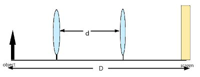
    • Set the apparatus as in figure below ensuring that the distance between the object and the screen is more than 4f where f is the focal length estimated above.
    • Obtain the image of the illuminated object on the screen when the lens is at position L1
    • Without changing the position of the object on the screen, move the lens to position L2 where another clear but diminished image is formed on the screen as shown below.
    • measure u and v for position L1 and the new distance u1 and v1 for position L2.
    • Determine the displacement d .
    workings

    from the diagram above,the distance between the point object and the screen is s. from the diagram, it is shown that the distance s is given by u+v.

    i. e. s = u+v ………………………………..(1)

    The distance between new and original position of the lens will be given by

    d=u’-u where u’ is the new object distance and u the original object distance

    d can also be obtained from v-v’ which is the original image distance and image distance when the lens is displaced by distance d.

    i.e d=u’-u and d = v-v’

    but u’=v and v’=u

    and therefore:

    d=v-u………………………………….(2)

    adding (1) and (2);

    hence s+ d= u + v + v –u

    and so: s + d = 2v and hence

    similarly we can subtract equation 2 from 1 as shown:

    hence s- d = u + v –v + u

    therefore : s- d = 2u and hence

    from the lens formulae:

    we can substitute values of u and v in terms of s and d as obtained in the expressions above. And hence;

    finding the lcm of the denominator, we obtain;

    and simplifying the above equation in the numerator:

    and finding the reciprocal so that we can get f;

    from the above equation: s2-d2 = 4fs

    a plot of s2-d2 against s results to a straight line through the origin with a slope equal to 4f.

    different values of s are obtained by changing distance between the object and the screen and then calculating the corresponding distance d.

    The two positions L1 and L2 that represents different positions of the lens are known as the conjugate points.

    Related topics


  • Listening is an art

    Listening is an art

    What’s something most people don’t understand?

    Most people really listen. This is because listen is hard work. We are not always inclined to be good listeners, but we are always distracted by many things when we are listening to somebody speaking. In fact most of people when they are having a conversation with some one, they spend a good part of their brains thinking about what to say in response to what the speaker is saying, consequently, they loose details of the speech in the process. In fact, experts in communication says that an original message is distorted as it passes from one person to another, one reason for this is because of our poor listening habits.

    If we could nurture the habit of effective listening, maybe there would be lesser arguments, quarrels and conflicts. When other people are talking, we should stop this habits of trying to insert and to stamp our stand on what they are saying but strive to understand their point of view. Our desire to safeguard what we know can be found from the way we keep interjecting when someone is speaking but not in seeking clarifications or reciting what they have just said, but to express our opinion and show our experience on the subject in discussion. This way we may loose a valuable wisdom we could have gained from the speaker, because we delighted on talking than listening.

    How should we listen?

    learn more about communication on the communication skills at precisestudy.online

    Related topics


  • Determining focal length of a lens by Non-parallax technique

    Determining focal length of a lens by Non-parallax technique

    A bulb is placed behind a hole with a cross wire on a cardboard so as shown in figure below. A lens on a lens holder is placed between a mirror and the cardboard.

    The cardboard together with the source of light is moved along the metre rule until a sharp image of the cross wire is formed along the cross wire object as shown. The figure shows two rays emerging from the point source towards the mirror through the lens

    The lengths f gives the focal length of the lens.

    Explanation

    The ray striking the mirror are reflected back along the same paths of the incidence so that the image of the source coincides with the source itself. This image can be received on a screen placed at the same position as the source as shown.

    If both the lens and the mirror are perfectly vertical or parallel to each other, the image perfect coincides with the illuminated object hole so that it cannot be seen, it is therefore necessary to tilt either the lens or the mirror a little so that the image can be mapped besides the hole.

    some equivalent arrangement is as shown.

    In the above arrangement, the object pin is moved towards the lens or away from it until when it coincides with it’s inverted image and this occurs when the pinhead is vertically above the center of the lens.

    At a point where the object and the image perfectly coincides, there is no relative motion between them as the eye is moved perpendicular to them and instead, they move together as one.

    The distance between the pin and the lens is then measured as the focal length of the lense.

    NB: Focal length increases as thickness of the lens decreases. This is because thick lenses refracts and deviates light more sharply than a thin lenses. Therefore, rays emerging from thick lens tends to converge earlier because because of the sharp bending in the lens.

    Related posts

  • Upthrust in Gases

    Upthrust in Gases

    Just like liquids, gases exerts upthrust on objects that are in them.Air is the most common gas whose upthrust maybe of interest because we float objects on air and sometimes we use parachutes to float in air as human beings.

    The upthrust in air is small because air has lower density compared to most of substances.

    The density of air is about 1.3kgm-3 or 0.0013gcm-3.

    If we trap a gas that has a lower density than air in a balloon, then that balloon can float in air. For example hydrogen has a density of 0.09kgm-3 whereas helium has a density of 0.18kgm-3. Therefore a balloon filled with helium or hydrogen will rise on air provided density of the balloon fabric and air will be less than density of air.

    Consider the figure below that illustrates a balloon filled with air .

    If we consider the balloon filled with air to a certain volume, the weight of air in the balloon plus it’s fabric is greater than the weight of air displaced by the balloon, since the volume of air in the balloon is nearly equal to the volume of air displaced.

    The upthrust force on the balloon due to the air is thus less than the weight. The balloon therefore stay grounded because the it’s weight is less than the upthrust force that could set it up to float on air.

    That is W-U > resultant downward forces.

    If the balloon is filled with a gas which is has lower density compared to that of air, the weight of the gas plus the balloon fabric is less than the weight of the air displaced by the balloon, hence the upthrust force U exerted by the air on the balloon is greater than the weight W of the inflated balloon.the resultant upward force is greater than W-U and hence the balloon set to accelerate upward.see the illustrations below.

    Example Question
    solution
    Related topics

  • Density of mixtures

    Density of mixtures

    A mixture is obtained by putting together two or more substances such that they do not react with one another.

    Density of a mixture lies between the densities of the constituent substances and depends on their proportions.

    Volume of the mixture is obtained by summing up the masses of the individual constituents that makes the mixture and dividing it with the sum of their individual volumes. I.e

    Density of the mixture=mass of the mixture /volume of the mixture

    Related Topics


    References

    • Secondary Physics. 2nd ed., Kenya Literature Bureau, 2011, https://doi.org/KLB10524 20m 2012. pp. 8-48.
  • The Archimedes’s Principle

    It states that:

    When a body is partially or totally immersed in a fluid, it experiences an upthrust equal to the weight of the fluid displaced.

    The law of flotation

    It is a special case of the Archimedes’s Principle which states that:

    A floating object displaces it’s own weight of the fluid in which it is floating.

    Related Topics


  • Describing materials

    Describing materials

    A material is selected for a particular use depending on its ability to withstand forces it may be subject to. A given material has some attributes that defines it’s characteristic. The characteristics of a given material determines its suitability for a certain work.

    Some of the important physical characteristics of materials includes:

    Strength

    This is the ability of a material to resist breakage when under stretching, compression or shearing force. A material with much strength can be able to withstand a large force without breaking.

    Stiffness

    This is the resistance a material offers to forces which tend to change its shape or size or both. Stiff materials are not flexible and resist bending.

    Ductility

    It is characteristic of a material that give it a structure that can lead to permanent change of size and shape.

    Ductile materials are material which will elongate considerably under stretching forces and undergo plastic deformation until they break .

    Examples of ductile materials may include:

    • Lead
    • Copper
    • Wrote iron
    • Plasticine

    Ductile materials can be rolled into sheets, drawn into wires or worked into other useful shapes without breaking. They are usually very useful in making things like staples, rivets and paper clips

    Brittleness

    It is the characteristics of a material that makes it tend to break just after the elastic limit is reached .

    Brittle materials are fragile and do not undergoes any noticeable extension on stretching but snap suddenly without warning.

    brittle materials can only absorb a limited amount of energy before breaking.

    Examples of brittle materials includes:

    • Bricks
    • Glass
    • cast iron board
    • Dry biscuits
    • ceramic
    • graphite
    • diamond
    • crystal
    • Porcelain
    • Tin-rich Bronze
    • Sodium Chloride
    Elasticity

    Elasticity is the ability of a material to recover it’s original shape and size after the force causing it’s deformation is removed. Materials that regain their shape after deformation under force are said to be elastic.

    Elastic materials recovers to their previous shape after enduring deformations like compression and expansion

    A material that does not recover but is permanently deformed is said to be plastic.examples of elastic materials includes:

    • Rubber
    • springs
    • wires
    • Trampoline
    • Rubber Bands
    • Elastin
    • Nylon
    • Lycra
    • Gum
    • Wool
    • Silicon
    • Polyester
    • Balloons

    Related topics


  • Cause of Upthrust

    Cause of Upthrust

    Consider a cylindrical solid of cross-section area A which is totally immersed in a fluid of density ρ as shown.

    The pressure due to liquid column is usually given by P=ρgh.

    Pressure at the top of the solid will be given by, PT = h1ρg.

    Where h1 is the height of the liquid column above the top of the object.

    Pressure at the lower end of the object will be given by

    Pb=h2ρg where h2 is the height of the liquid above the lover surface of the cylinder .

    The pressure at the top of the cylinder will provide downward force exerted by the liquid up on the object.

    From the pressure laws, F=pressure P x Area A.

    i.e F=PA.

    Taking the area of the cylinder at the top, the force from the liquid acting on that surface is Given by F=PT x A=h1ρgA.

    Similarly, pressure at the bottom is given as F=PB x A=h2ρgA.

    The total resultant upwardward force F is this given as

    F=F2-F1

    Hence F=h2ρgA-h1ρgA

    Factoring out the common factors: F=ρgA (h2-h1)

    Let h be the difference between liquid column on top and the one at bottom h2 such that h=h2-h1

    Hence F=ρgAh

    But Volume is always given by V=Ah

    The resultant force F is the upthrust force U and will thus be expressed as.

    F=U=Aρpg=pgV

    where V is the volume of the liquid displaced.

    Mass of the liquid is usually given by density x volume. Hence mass m of liquid displaced will be given by m=Ahρ

    Weight is usually given as Weight W=mg

    Hence weight of liquid displaced will be W=U=Ahρg which represents the upthrust force we calculated earlier. This confirms the archimedes principle that upthrust force is equal to the weight of the fluid it displaces.

    From our mathematical arguments, it should be easy to see that Magnitude of the upthrust force is equal a function of volume of the object and density of the liquid considering that gravitational pull g is a constant.

    Related topics


  • Effect of Magnetic field on current

    Effect of Magnetic field on current

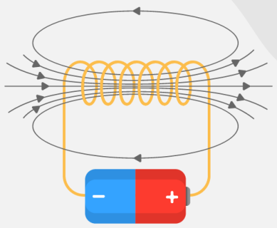
    Professor Hans Oersted discovered that a conductor carrying current has magnetic field associated with it in 1820.

    This discovery has led scientists to always interfere magnetic field with electric fields causing development of many devices that has become very instrumental in human life. These devices includes electric motors, loud speakers, coil meter, circuit break, magnetic tapes, electric motors etc.

    To investigate magnetic effect on electric current, we consider two compasses , one placed on top of a current carrying wire and the one one placed under it as shown below.

    The compass is held on current conducting wire with the compass needle in line with the wire. And when the switch is closed , the compass north pole deflects as shown relative to direction of current for compass under wire.

    The deflection will be as shown when current is over the wire.

    When current is increased, by reduced resistance through a rheostat, the compass needle deflection increases.

    Suppose now we change the direction of the current by reversing the batter polarity, the direction of the deflection is observed to change to the opposite direction as shown

    When circuit is broken, the compass needle returns to it’s original position such that the north is in parallel with the wire showing no deflection.

    see the figure below:

    Magnetic needle position on wire with no current

    The above illustrations shows that magnetic deflection occurs only when there is current that is passing through the conductor.

    This simple experiments confirms that there is association between magnetic field and electric current and that the association is dependent on number of factors like.

    • Direction of current
    • Direction of magnetic field
    • Magnitude of the current flowing
    • Strength of the magnetic field

    Explanations

    A flow of current is basically a flow of charge. Flowing charges has magnetic fields associated with them which can be observed when a magnetic compass is made to interact with current conduting wire.

    Strength of magnetic field created by flowing current increases with increase of the flowing current which can be shown by greater deflection on a magnetic compass when current in wire is increased.

    Somebody called Ampere is the one that devised a rule called Ampere’s swimming rule that physicists can use to predict direction of compass deflection when it encounters a current flowing in a wire.

    The Ampere’s rule states that:

    Related topics


  • Phase and Phase Difference

    Phase and Phase Difference

    The word phase in normal usage means any stage in a series of events or in a process of development.

    cambridge University dictionary defines phase as one of the stages or points in a repeating process measured from a specific starting point.

    Two Waves can be of the same amplitude but with the different frequencies as shown in figure below.

    The wave profile P makes it’s one complete oscillations before wave Q. Wave P has shorter wavelength compared to Q and hence P has higher frequency.

    We can also see that P has smaller period as waves with shorter wavelength has smaller period.

    Wave P completes it’s first cycle at A while Q finishes it’s first oscillation at B. We can say that P is leading Q. The maximum displacement of the two waves is the same hence they are operating at the same amplitude but different frequency. The two waves are said to be out of phase.Think about two radio receivers tuned to two different stations but with equal volume.

    waves can also be of the same frequency but different amplitudes. Think of when we tune in our two radio receivers to the same station and then set them at different volumes

    The figure below illustrates two waves operating at same frequency but at different amplitudes.

    As can be seen from the diagram, one wave is having more displacement than the other one but they are arriving at the same horizontal position simultaneously. We say they are in phase.

    Pendulum bobs in phase

    To further illustrate the concept of phase and out of phase oscillations, consider two identical pendulums with bobs P and Q below.

    The two masses, P and Q are set in oscillation by giving them some displacement on the left and then releasing them simultaneously. Because they have equal displacement and released at the same time , they will pass through the lowest point Y at the same time as they move on to the opposite direction.. They attain displacement together at Z and swing back together to complete the oscillation at x.

    At any particular moment, the two masses will be moving in the same direction and at the same level of displacement in their oscillations.The masses are said to be oscillating in phase.

    Particles in a wave motion which happens to be oscillating in the same direction and at the same level of displacement in their oscillation are said to be in phase.

    The diagram below have highlighted two positions of particles A and B. The particles are in the same displacement level from the reference line and they are both facing the same direction as indicated by the arrows. The particles A and B are said to be in phase and their distance apart is the wavelength λ of the wave motion whereas time taken to move from A to B is the periodic time T.

    Particles in a wave motion can be in phase even if they have different amplitude.

    In our previous pendulum oscillation of mass P and Q ; If P is Initially given a larger displacement than Q, the two will oscillate i n phase even though P will always be at a larger magnitude of displacement than Q.

    A typical displacement time graph for two wave motions in phase with different amplitudes is shown below.

    two waves in phase at different amplitude.

    Oscillations out of phase

    Consider two masses P and Q displaced from opposite directions from each other as in figure below.

    When released simultaneously, they pass through the rest position at the same time as they move in the opposite direction and they reach a point of maximum displacement at the same time but their maximum displacement is in opposite direction to each other.

    180o out of phase

    The two objects above are always at the opposite levels of displacement and their oscillations opposite direction to each other and they are said to be in opposite phase.

    Wave motions that have same displacement and makes complete oscillations at the same time with their maximum displacements in exact opposite to each other are said to be in 180o phase difference (180o out of phase).

    The figure below shows two wave motions at 180o phase difference.

    90o out of phase

    suppose in our pendulum oscillations we displaces the objects P and Q to X ; we release Q before P and then we release p when Q is exactly at Y. The angle of oscillation between P and Q will be 90o in difference and the resulting oscillation will be 90o out of phase.

    The displacement time graph for waves 90o out of phase is illustrated below.

    two waves can be out of phase at any angle. We are likely to see that in our future lessons

    Related Topics