Density is mass of a substance contained it it’s unit volume.
Density is usually represented by rho (ρ)
The SI Unit of density is kilogram per cubic meter, that is; (kgm-3)
A common unit of density is grams per cubic centimeter (gcm-3) which is very common in day to day measurement of density.
Formula for density
we can use symbols alone to write expressions about density when solving problems involving density.
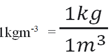
we should be able to convert densities expressed in Kilogram per cubic meter(kgm-3) into grams per cubic centimeter (gcm-3). In many cases, conversion from on unit of measurement to another is usually necessary. Let say we want to change 1kgm-3 into grams per cubic centimeter (gcm-3) . 1kgm-3 means that:
Now we convert 1 kg into grams remembering that, 1 kg =1000 grams and 1 cubic meter into cubic centimeters;
remembering that 1m3 = 1000000 cm3
hence 1 kgm-3 = 0.001 gcm-3
then dividing by 0.001 gcm-3 on both sides:
hence 1 gcm-3 is equivalent to 1000 kgm-3
Example
The density of a substance in a lab is expressed as 5g/cm3. Express it’s density in SI Unit.
solution
The SI unit of density is kilogram per cubic meter. We therefore change grams into kilograms and cubic centimeter into cubic meter.
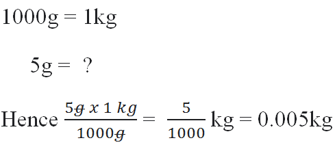
expressing density in terms of grams and cubic centimeters:
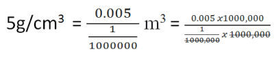
1 000,000 cm3 = 1 m3 hence :
hence
=5000 kgm-3
Practice Questions
A glass block measures 180mm by 80 mm by 20 mm. It’s mass is 280 g. Determine it’s density in SI Units
A certain metal has it’s density given as 1.9gcm-3. If 50000 kg of such metal was purchased by a company. what volume did it occupy?
The lens formula is an equation that shows the relationship between the focal length of the mirror, the image distance and the object distance.
The object distance usually determines the image distance but the lens formula also suggests that, focal length determines what image should formed on the screen. The focal length is proportional to the the thickness of a convex lens. The thicker the convex lens, the shorter the focal length.
Thick lens means rays of light are refracted more quickly compared to when the lens is thin.
The lens formula is stated as:
If we can describe the lens formula in a verbatim form, then we can say that, reciprocal of the focal length is equivalent to sum of the reciprocals of object distance and image distance.
Deriving Lens Formula
consider a an object O of height OB placed between 2F and F. Using the first two rays to obtain it’s image ; The two rays of right, object height and image height together forms triangles that can be used to describe geometrical relationship in the diagram that can results to lens formula.
PO = image distance u
PI = image distance v
PF = focal length f
OB = PH
Triangles POB and PIM are similar hence;
triangle PFH and FIM are similar and therefore.
where f = PF
FI = PI-PF = v – f
hence;
and so
cross multiplying the above equation we obtain the following expression;
u(v-f)=vf
and expanding the bracket we get;
uv-uf=vf
and making uv the subject;
uv = vf + uf
factoring out f we get:
uv = f(v+u)
and then dividing by f on both sides of the equation;
dividing by uv on both side to get:
where
and therefore:
The formula holds true for both convex and concave lens.
However, sign-convection is adopted where virtual image and focal length are given negative sign and considered positive if real.
Example
An object of height 20 cm is placed 25 cm in-front of a convex lens of focal length 18 cm. calculate image distance, image height and magnification.
solution
Magnification M = (64.28)/25 = 2.57
so the image is real and magnified. it is real because it’s image distance has a positive value and it is magnified because it has M greater than 1.
Example
An object of height 3 cm is placed 8 cm infront of a convex lens of focal length 15 cm. Find the position, nature and magnification of the image.
Example
An object of height 20cm is placed 30 cm infront concave lens of focal length 25 cm from the lens. Determine:
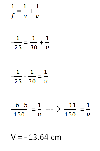
(a) The image distance
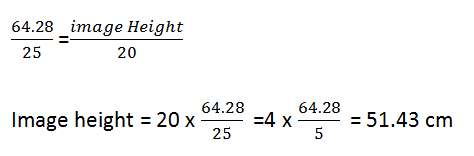
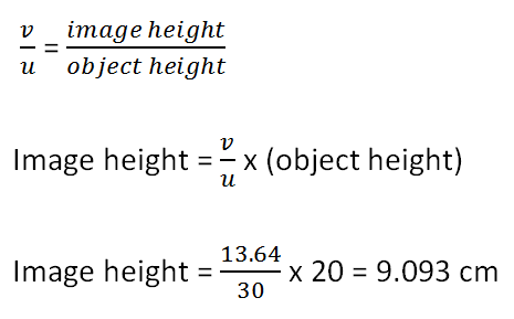
(b) height of the image
(c) magnification
solution
(a)
f=-25 cm (negative because concave lens have unreal focal point.
u = 30 cm
(b)
(c)
Practice Problem
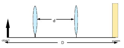
A lens forms an image that is 6 times the size of the object on a screen. The distance between the object and the screen is 120 cm when the image is sharply focused.
An object of height 10 cm is placed 30 infront of convex lens of focal length 20 cm. Use scale drawing to find position, size and nature of the image and Magnification.
solution
we use the scale of 1cm to represent 10cm horizontally and 1cm to represent 10cm vertically. The object is represented by an upright arrow that is placed 30cm on the principal axis from the line that represents the lens.
object distance = 30cm
image distance =60cm
height of image =20cm
height of object=10cm
The image is magnified as it is bigger than the object.
The image is position at 60cm which is beyond 2F on the other side of the lens. It is a real image
Magnification M = (Image distance/object distance) = 60cm/30cm = 2
Heat is a form of energy that flows as a result of temperature difference between two points or region where it passes from a body at higher temperature to the body at lower temperature.
Heat can also be defined as the energy that flows from places of high temperature to places with low temperature.
A body that receives heat has it’s temperature being increased and a body that looses heat has it’s temperature lowered.
If two bodies are at different temperature in the same environment, heat flows from the body at high temperature to body at low temperature until the two bodies are at the same same temperature which is usually a temperature that is between the two initial temperatures. The two bodies are then said to be in thermal equilibrium.
The SI unit for heat is joule(J).
There is no instrument to measure heat directly but when we see a body rising in temperature, we know it has absorbed heat. However, we will expound more on how to measure heat in future lessons.
Heat flow is responsible for the presence of wind in our environment.
What is temperature?
Temperature is the quantity that measures degree of hotness or coldness of a place or an object.
When we talk about degree of hotness, we talks about the feeling. Not a very good way of describing a scientific phenomena. But a more technical definition of temperature is that temperature is the quantity that describes the average energy of particles in a material.
A large heat can cause very little rise in temperature of a substance but also small absorption of heat can cause large increase of temperature. So heat is usually described as the total amount of energy that flows from a body at high temperature to a body at lower temperature.
The temperature change caused by a given heat on a substance depends on the mass of the object and the internal molecular structure of the substance, which is usually known as the heat capacity of the substance.
Heat is measured in joules( the unit for energy) but temperature is measured in Kelvin.
Temperature is a basic physical quantity whereas heat is a derived quantity.
Modes of heat transfer
The common methods by which heat traves from one point to another includes:
Conduction
Convection
Radiation
Conduction
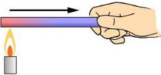
Heat conduction is a process where molecules that are close to the source of heat picks up the heat, vibrates faster and passes on the excess heat to their immediate neighbouring molecules.
The neighboring molecules upon receiving energy from their neighbors increases their vibrations but with with a slower later than the molecules that gave the the energy since they got just a small part of the supplied energy. Therefore, temperature reduces along the material as one moves away from the source.
Convection
Convection is the transfer of heat by the actual movements of the molecules where molecules that receives heat becomes lighter and moves up to allow colder molecules to come to regions of heat.
Convection is the most important means by which heat is transferred in liquids and gases.
Convection can be described as the continuous flow of liquid and gas particles in a complete loop due to a difference in temperature.
Radiation
It is a method of heat transfer by means of electromagnetic radiation.
Electromagnetic radiation are waves that does not need material medium to transfer.
Electromagnetic waves moves the same way, heat from the sun reaches the earth service as it travels without aid of any medium.
Mass is the quantity of matter in a substance. Matter is anything that occupies space.
The mass of an object depends on it’s size and the number of particles it contains.
The SI unit of mass is the Kilogram (Kg).
A kilogram is the mass of a piece of platinum-iridium metal kept at Sevres, near Paris,France at the International Office of Weights and measurements. That piece of metal kept in France is the standard with which all masses of the world are measured with the kilogram unit.
though kilogram is the SI unit, the most common unit of measuring mass is the gram.
The following table shows sub-units of gram and kilogram
Prefix
number of grams (g)
Kilogram (Kg)
1000 g
Hectogram (Hg)
100 g
Decagram (Dg)
10 g
decigram (dg)
(1/10) g
centigram (cg)
(1/100) g
milligram (mg)
(1/1000) g
microgram (µg)
(1/1000,000) g
nanogram (ng)
(1/100,000,000) g
picogram (pg)
(1/1000,000,000,000) g
tables of conversion of grams
1 kg = 1000 tonnes
other units used to measure mass includes:
1 pound (lb) = 0.4536 kg)
1 ounce(oz) = 0.02835kg
Though different weights are experienced depending on gravitational pull of a place, the mass of an object remains constant beacuse number of particles in an object will not change with change of location.
Instruments used to measure mass
Platform balance
Electronic balance
The object whose mass is to be measured is placed on the pan and its weight causes electronic circuit to develop current to display the mass on the digital display. It is a very accurate instrument and is useful in laboratories especially small masses.
Beam balance
works by the principles of moments.
The object whose mass is to be measured is balanced against a known standard mass on as equal arm lever. The beam balances when the mass of the object is equal to the standard mass.
Table balance
works under principles of moments
Spring balances
uses laws of gravitational pull
postal balance
Roman Steelyard Balance
Exercise
convert the following as instructed
1500 tonnes to kg
200000000000 mg into Kg.
256 g into tonnes
0.000000000000000000 567 tonne into pg
12.43 g into mg
Problems involving mass
Sheila went to the grocery store and bought a 3 watermelons that weighed 4.4 kilograms and a bunch of bananas that weighed 750 grams. She also bought a bottle of juice that contained 1.2 liters.
a) Convert the weight of the watermelon from kilograms to grams.
b) If Sarah bought 3 bottles of juice, how many grams of juice did she buy in total if density of juice is 1.25gcm-3?
c) If each banana weighs 125 grams, how many bananas did Sarah buy?
Images formed by lenses has different features based on where the object is positioned with respect to the lens.
There are different region along the principal axis where object can be positioned and each region will determine kind of image obtained.
The regions considered includes:
Beyond Center of curvature C
Object exactly at C
Object between C and F
Object exactly at F
Object between F and the optical center of the lense
Object at infinity
We will now consider each of the positions and examine the kind of images formed.
Object at infinity
Object at infinity is object that is at large distance in respect to the focal length of the lens.
When you focus a distance object, there is that distance between the screen and the lens where the sharp clear image is formed, the distance between the screen and the lens is the focal length and the point where the image is formed is the principal focus of the lens. See the diagram below.
A photo showing image formed for trees some distance from the laboratory
when you focus on distance object such that a sharp image is formed on a white screen as in figure above, then the distance between the screen and the lens is the approximate focal length for the lens.
The rays diagram for the convex lens focusing distance object is shown.
The figure below shows two rays from infinity coming from opposite sides of the principal axis.
The characteristics of image formed when object is at infinity.
Real (formed on the screen)
Inverted
Diminished (smaller than worship
Formed at F
The setup of lenses is used in the objective lens of a telescope.
Object beyond 2F
The characteristics of image formed is
Real
Inverted
Diminished
Formed between F and C on the side of the lens
Object beyond C is a useful setup for cameras and in human eyes
Object at 2F
The figure below shows the image formed by concave lens when an object is exactly at 2F, that is, image at center of curvature of the lens.
The characteristics of images formed includes:
Real
Inverted( upside down)
Same size as the object
Formed at F on the opposite side of the lens
Object at F is a useful setup in terrestrial telescope
Object between F and 2F
It is the only position we have a magnified real image . The image formation is as shown in figure below.
image formation when object is between 2F and F
The characteristics of images formed is:
Real
inverted( upside down)
Magnified (bigger than object)
Formed beyond 2F on the other side of the lens.
Object between F and 2F is a useful setup for microscope objective and photographic enlarger.
Object at F
When object is placed at F, The image formation is as shown in the diagram below
concave image formation for an object at F
The rays emerge parallel after refraction by the lens and is formed at infinity.
A good example of rays of light moving to infinity is rays of light coming from a spotlight, Therefore the object at infinity setup is common in searchlight and spotlights.
Object between F and the lens p
when object is between F and the lens, the rays of light don’t converge but diverge, but if extended backwards, they seems to meet behind the object.
The between F and lens is the only position where the convex lens produces virtual and upright image. The figure below shows image formed when object is between F and the lens
The characteristics of image formed is
virtual
erect
magnified
on the same side as object
Object between F and P is useful in magnifying glasses and the microscope.
Image formed by Diverging lenses
Unlike Convex lens, the image formation by concave lenses does not depend on position of the object but it is always virtual, erect and diminished and the image is always formed on the same side as the object.
The figure below shows formation of an image by concave lens when the object is between 2F and F.
The following shows an image for concave lens when an object is between F and the lens.
conclusion
Images formed by concave lenses depends on the position of the object but. The image by concave lenses are virtual only when it is between F and the lenses.
The image by concave lens does not depend on position of the image. Regardless of the position of the object from the lens, the image is always virtual, diminished and upright.
In books, we use ray diagrams to represent images formed by thin lenses. Ray diagrams are straight lines with arrows that shows direction of light rays.
Points to note when drawing ray diagrams
Real rays and real images are drawn using solid lines
virtual rays and virtual images are drawn in broken lines
To locate the image, two of the three important rays are drawn from the tip of the object towards the lens. The first ray parallel to principal axis and through principal focus, the second ray from the tip of the object through the optical center or the third that passes through the principal focus before moving parallel to the principal axis.
Where two or more rays intersect after refraction by the lenses is the tip of the image.
if the object stands and is perpendicular to the principal axis, the image is also perpendicular to the principal axis.
To complete the image, a line is drawn perpendicular to the principal axis from the tip of the image
If the foot of the object crosses the principal axis, two of the three rays used to locate image should be drawn for both the tip and the foot of the object. A point object for the image tip should be joined with point image of the foot to get the desired image.
converging lenses are represented by the following diagram in drawings:
symbol used for convex lens
concave lenses is usually represented in the diagrams by the picture below.
symbol for concave lens
Example problem
An object 15cm tall has been placed 32cm from a concave lens of focal length 20 cm. By scale drawing, determine:
(a) The position of the image formed
(b) Magnification of the image
(c) The height of the image
solution
We use the scale of 1 cm to represent 5 cm and using two rays to form an image, the resultant image after reflection is as shown
(a) From the diagram, one can see that the image is formed 52cm from the lense.
(b) From the diagram, the height of the image from the principal axis is 24 cm.
substituting for the values of hi and ho, we have:
The same result could be obtained by finding ration of image distance to object distance with some slight variation that comes with measurement errors:
(c ) From the scale diagram, the height of the image is about 24.5cm
Remarks:
The diagram can aslo be used to give further insights about the image formed. For example we can see it is upside down, it is formed by two rays actually meeting, hence the image is real.
Also the image is taller than the object, hence it is magnified just by looking
An image is formed when two or more rays meet at a point. In actual sense, millions of rays meet for an image to be formed. When rays meet and forms an image, the image formed is refered to as a real image.
When determining images formed by a lens, we consider a ray from a point object. Appoint object is a tiny point from the object.
Image formation works just the way eyes work. For you to see any object, rays of light must fall onto the object and then be reflected into your eyes, so that your eyes can form the image about the object on the retina.
The rays must converge after passing through the eye lens for the image to be formed on the retina. Similarly, thin convex lenses converges the rays that fall on it to form an image of the object. The rays of light falls on the object before they are reflected towards the lens.
There are three important rays we use to show image formation by lenses.
These rays are:
A ray reflected from an object that moves parallel to the principal axis and is refracted such that it passes through the principal focus or appears to emerge from the principal focus after refraction.
A ray diagram showing a ray of light from distance object that passes through principal focus after refraction
For a diverging lens, the ray will only appear to be coming from the principal focus as shown
A ray parallel to principal axis that appears to come from principal axis after reflection
A ray that passes from the object and towards the optical center of the lens that passes through the lens undeviated.
A ray diagram showing a ray from distance object that passes through the optical center undeviated.a ray passing thought optical center of concave lens undeviated
A ray that passes from the object and passes through the principal focus and that will move parallel to the principal axis after it it is being refracted.
A ray reflected from an object and passes through principal focus before being refracted by the lens so that it moves parallel to the principal axis.a ray that seems to pass through the principal focus after being refracted to be parallel to principal axis by a concave lens
Meeting of any two rays out the three mentioned will be sufficient to represent an image on a diagram.
The diagram below shows the three rays meeting at a point to form an image of the object
We usually use an upright arrow to represent an object.
for a concave lens, the image formation is imagined by the eye as illustrated below.
Conclusion
image formation needs at least two rays to meet.
Three rays are common is identifying an image.
Image formation by concave lenses is very different from that of concave lens.
Next lesson we will discuss image formation by concave lens.
Thin lenses have their own vocabulary mostly that describes various parts of the lens. This parts includes:
Center of curvature C
Radius of curvature R
Principal axis P
optical center O
Principle Focus F
Focal Length f
Focal plane
We will discuss all the highlighted parts in this lesson
Center of Curvature C
It is defined as the center of the sphere of which the surface of the lens is part.
We consider the lens to have been cut off from a transparent sphere of radius R. In other word, the lens is part of a curved surface of a certain sphere as illustrated below.
For bi-convex lens, the lens is considered to come from two pieces cut from two different spheres and combined at the inner side. Consider the illustration below where we extract service1 and service2 from two spheres.
sphere for surface1
sphere for surface2
Because the bi-convex comes from two spheres, it will have two centers of curvature which will be opposite to each other.
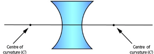
similarly the bi-concave lens is derived from two spheres as illustrated.
Different parts from spheres will be joined two have a concave lens that has two centers of curvature as shown below
Radius of curvature
It can be defined as the radius of the sphere from which the surface of the lens is part.
It can also be defined as the distance between the Center of curvature and the optical center o of the lens.
Principal axis
It is an imaginary line passing through the centers of curvature and is perpendicular to the plane of the lens.
Optical center
It is the geometric center of the lenses where a ray incident to the lens passes on undeviated.
Principal focus
Sometimes also referred to as the focal point. It is a point on the principal axis where rays parallel and close to the principal axis converge after refraction by a convex lens or where the rays parallel and close to the principal axis seems to diverge from after refraction by a concave lens.
The figure below illustrates convergence of parallel rays of light at principal focus after refraction.
showing a principal focus of a convex lens
The virtual principal focus of a concave lens is as illustrated below
A lens has two principal foci, and they are on either side of the lens.
The principal focus of converging lens is said to be real because their actual meeting of rays of light there.
The principal axis of diverging lens is said to be virtual (imaginary) because rays of light do not actually meet there.
Rays that are parallel and close to the principal axis or almost parallel to the principal axis are referred to us paraxial rays.
Rays parallel but far from the principal axis are referred to as marginal rays or axial rays.
Focal length f
It is the distance between the optical center of the lens and it’s principal focus.
By Convection, focal length of converging lens is considered real while that of diverging is considered virtual.
Focal plane
It is an imaginary plane that passes through the focal point and is perpendicular to the principal axis.
Focal plane is illustrated below
rays of light that are not parallel to the principal axis converges at a point on a focal plane or will appear to diverge from there after refraction
Conclusion
In this lesson we have seen that lens are pictured as being extracted from a sphere and the radius of the said sphere plays and important role in description of the lens. A lens converge or diverges rays parallel to the principal axis at the focal point.
Contains information related to marketing campaigns of the user. These are shared with Google AdWords / Google Ads when the Google Ads and Google Analytics accounts are linked together.
90 days
__utma
ID used to identify users and sessions
2 years after last activity
__utmt
Used to monitor number of Google Analytics server requests
10 minutes
__utmb
Used to distinguish new sessions and visits. This cookie is set when the GA.js javascript library is loaded and there is no existing __utmb cookie. The cookie is updated every time data is sent to the Google Analytics server.
30 minutes after last activity
__utmc
Used only with old Urchin versions of Google Analytics and not with GA.js. Was used to distinguish between new sessions and visits at the end of a session.
End of session (browser)
__utmz
Contains information about the traffic source or campaign that directed user to the website. The cookie is set when the GA.js javascript is loaded and updated when data is sent to the Google Anaytics server
6 months after last activity
__utmv
Contains custom information set by the web developer via the _setCustomVar method in Google Analytics. This cookie is updated every time new data is sent to the Google Analytics server.
2 years after last activity
__utmx
Used to determine whether a user is included in an A / B or Multivariate test.
18 months
_ga
ID used to identify users
2 years
_gali
Used by Google Analytics to determine which links on a page are being clicked
30 seconds
_ga_
ID used to identify users
2 years
_gid
ID used to identify users for 24 hours after last activity
24 hours
_gat
Used to monitor number of Google Analytics server requests when using Google Tag Manager