The function of a cell in a circuit is to supply electrical energy. By definition, the electromotive force (e.m.f.) of a cell is the potential difference between its terminals when no charge is flowing out of the cell (cell in open circuit).
Electric cells and batteries are essential sources of electrical energy in everyday life. From powering flashlights and radios to running vehicles and electronic devices, cells convert chemical energy into electrical energy. However, no cell is perfect. Every cell possesses a small internal resistance that affects the voltage supplied to an external circuit.
Figure below shows a circuit that may be used to demonstrate the difference between e.m.f. of a cell and terminal voltage.

The reading of the voltmeter when the switch is open is the e.m.f. of the cell.
Once a cell supplies current to an external circuit, the potential difference across it drops by a value referred to as ‘lost voltage’. This loss in voltage is due to the internal resistance of the cell.
The potential difference across the cell when the circuit is closed is referred to as the terminal voltage of the cell.
Relationship Between electromotive force and Internal Resistance
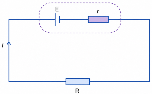
If a resistor is connected in series with a cell as shown in figure below, the internal resistance of the cell , is considered to be connected in series with the external resistor .

The current flowing in the circuit is therefore given by the equation;
where is the e.m.f. of the cell.
Thus,
=V+Ir
is the voltage drop across the external resistor R while Ir is the voltage drop across the internal resistance.
The voltage across the external resistor is called the terminal voltage while the p.d. drop across the internal resistance is called the lost voltage.
Battery Internal Resistance Animation
Explanation of the Animation:
- The blue moving dots represent electric current flowing through the circuit.
- Inside the battery, the battery emf (E) pushes charges through the internal resistance r.
- The orange glowing effect inside the resistor r shows that some electrical energy is lost as heat inside the battery.
- The external resistor R receives the remaining energy from the battery.
- Increasing internal resistance causes greater voltage loss inside the battery.
Experiment to determine the internal resistance and electromotive force of a cell
Method 1
Apparatus
Voltmeter, ammeter, rheostat, cells, connecting wires.
Procedure
- Connect the apparatus as shown in figure below

- Switch on the circuit and set the current to the minimum value possible.
- Increase the current in steps and record the corresponding terminal voltage in table below.
Table of current against voltage
| current I(A) | ||||
| Voltage (V) |
- Plot a graph of voltage against current.
Determining Internal Resistance of a Cell
set current with the slider
| Current I (A) | Voltage V (V) |
|---|
Results and Conclusion
The graph of voltage against current is as shown below.

Using the equation and hence V=E-Ir; the gradient of the graph gives the internal resistance of the cell.
If the graph is extrapolated so as to cut the voltage axis, the point at which it does so gives the electromotive force(e.m.f) of the cell.
Method 2
Apparatus
- Ammeter
- voltmeter
- variable resistor
- cells
- connecting wires.
Procedure
- Set the apparatus as shown:

- Switch on the circuit and increase the current in step from a minimum value.
- Record the corresponding voltage .
Complete table
| Current I (A) | ||||
| Voltage(V) | ||||
| R=V/I | ||||
| 1/I |
Plot a graph of against
Results and Observation
The graph is a straight line with a positive gradient. see the diagram below

The gradient of the graph gives
Internal resistance can be obtained in two ways:
(i) Extrapolating the graph to cut axis gives as can be observed on the diagram above.
(ii) If the intercept on axis is , then,
So,
But:
Therefore,
Example 20
A battery consisting of four cells in series, each of e.m.f. 2.0 V and internal resistance 0.6 Ω, is used to pass a current through a 1.6 Ω resistor. Calculate the current through the battery.
Solution
Current through battery =
The electromotive force(e.m.f) of the battery is the sum of the e.m.f. of all the cells while the internal resistance of the battery is the sum of all internal resistances of the cells.
Therefore, current through the batter
Example 22
A cell drives a current of 2.0 A through a 0.6 Ω resistor. When the same cell is connected to a 0.9 Ω resistor, the current that flows is 1.5 A. Find the internal resistance and the electromotive force(e.m.f) of the cell.
Solution
The first connection is as shown with it's internal resistance.

when connected to 0.9 ohm resistor, the circuit is as shown:
Taking E as the electromotive force(e.m.f) of the cell and r the internal resistance.
E = IR+Ir
from the below figure:

E = (2.0 x 0.6)+2.0r = 1.2+2r --------(i)
using the figure below:
E = (1.5 x 0.9)+1.5r
E = 1.35 + 1.5r ---------(ii)
since e.m.f is the same in both circuits:
1.2+2r = 1.35+1.5r
2r-1.5r = 1.35-1.2
=.5r = 0.15
r = 0.3Ω
substituting for r in the first equation:
E = 1.2+2r = 1.2+2(0.3)
E= 1.2+0.6 = 1.8V
Example problem
A battery consists of two identical cells, each of e.m.f. 1.5V and internal resistance 0.6Ω, connected in parallel. Calculate the current the battery drives through a 0.7Ω resistor.
Solution
When identical cells are connected in parallel,the equivalent e.m.f. is equal to that of only one cell.
The figure below represents the arrangement:

The equivalent internal resistance is equal to that of two such resistors connected in parallel as shown in the diagram above. Figure (a) is simplified to figure (b).
Equivalent e.m.f.
Equivalent internal resistance will be given by:
substituting:
Current through the will be given by:
Example 23
In an experiment to determine the electromotive force and internal resistance of a cell, the following results were obtained.
| I (A) | 0.5 | 1.0 | 1.5 | 2.0 | 2.5 |
|---|---|---|---|---|---|
| V (V) | 1.25 | 1.0 | 0.75 | 0.5 | 0.25 |
Plot a graph of against . From the graph, determine the values of and .
Solution
A table for and is generated from the values given as follows:
| 2.0 | 1.0 | 0.67 | 0.5 | 0.4 | |
|---|---|---|---|---|---|
| | 2.5 | 1.0 | 0.5 | 0.25 | 0.1 |
A plot of against is as follows:

The graph is a straight line whose gradient is
Thus,
Hence,
The value for is found by extrapolating the graph until it cuts the R-axis and reading off as indicated on the graph.
Thus, r=0.48Ω
Alternatively
Thus,
Practice Questions
- State the physical quantities whose units are;
- ampere,
- ohm,
- volt,
- coulomb and watt.
- State Ohm’s law and describe an experiment to verify it.
- For the resistor network given, determine
(a) the total resistance
(b) the voltage drop across each resistor.
(c) the current through each resistor.

- The figure below shows four resistors and a source of voltage of with internal resistance

(a) Find the effective resistance of the circuit.
(b) Calculate the current through .
- Six resistors are connected in a circuit as shown in the figure below.

Calculate the:
(a) total resistance of the circuit.
(b) total current in the circuit.
(c) current through the resistor.
(d) current through the resistor.
- (a) You are provided with two resistors of values and .
(i) Draw a circuit diagram showing the resistors in series with each other and with a battery.
(ii) Calculate total resistance of the circuit (assume negligible internal resistance).
(b) Given that the battery has an e.m.f of 6V and an internal resistance of 1.33Ω:
calculate the current through:
(i) 8Ω
(ii) 4Ω resistor when the two are in parallel.
practice questions
Quick Check: Electromotive Force & Internal Resistance
1. What does EMF represent?
2. A battery has an EMF of 12 V and an internal resistance of 2 Ω. If the current is 3 A, what is the terminal voltage?
3. Calculate the current when a battery of EMF 9 V and internal resistance 1 Ω is connected to a 8 Ω resistor.
Leave a Reply